
Process Accessories
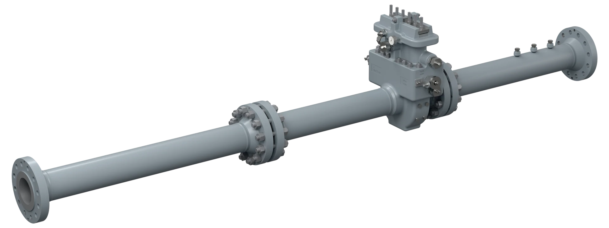
The parts that go around the primary element and are usually ordered late, from a different supplier, in the wrong material. Machined here to the same certification as the elements, with manifolds sourced to the same specification, so one order covers the whole measurement point.
Five families
Each is specified against the same process data as the flow element it sits beside, which is the point of buying them together.
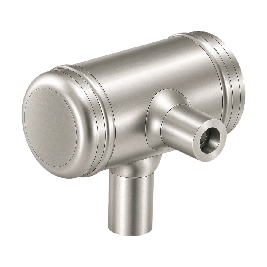
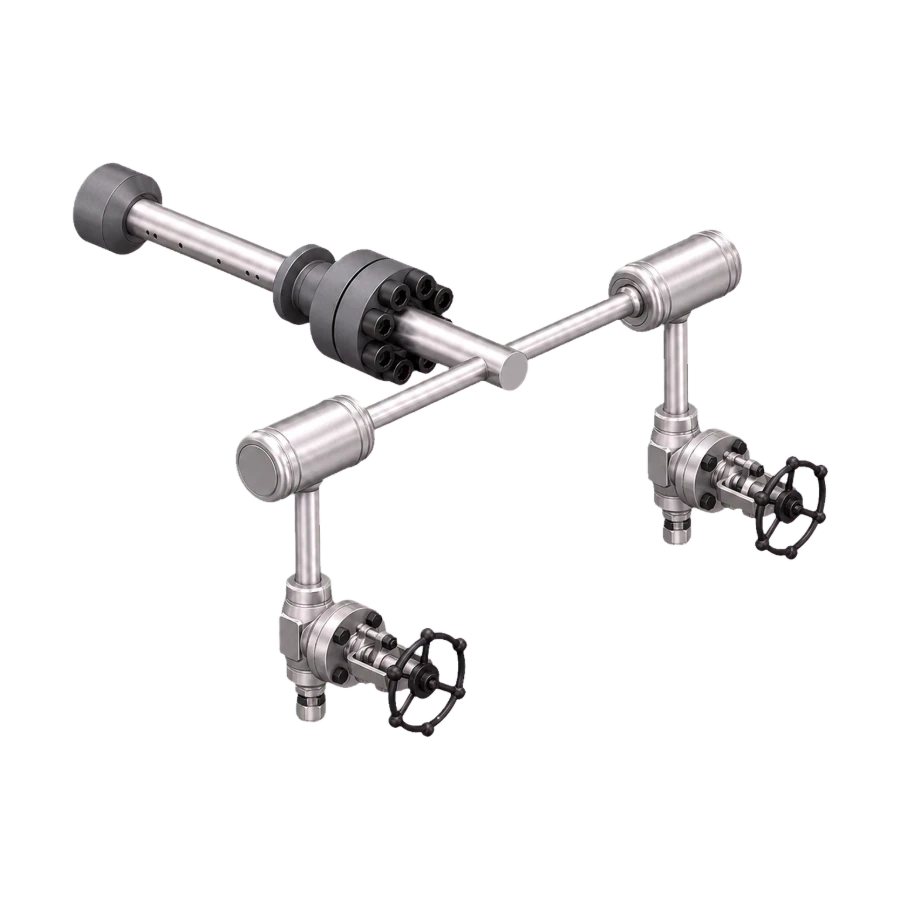
Condensate Chamber
Seal pots for steam service
A short horizontal vessel with welded caps and side connections at set heights, keeping the impulse legs full and equal on steam and other condensing media.
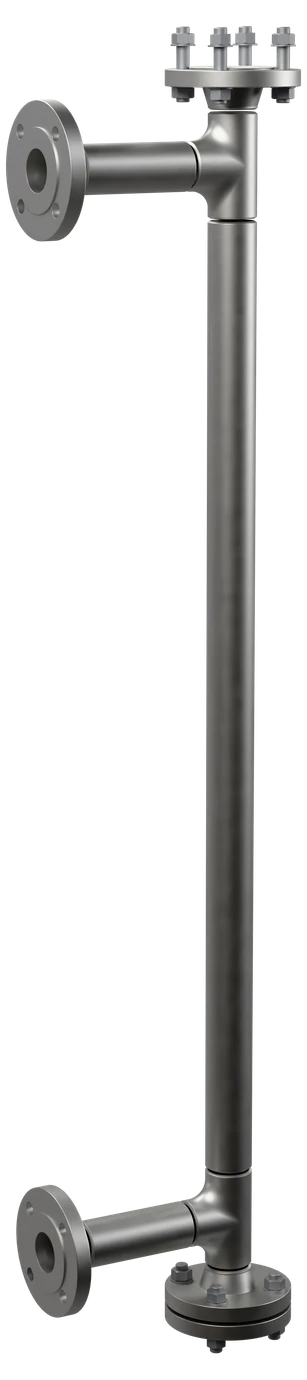
Level Tube
Gauge glass and standpipe assemblies
Vertical standpipe with flanged process connections top and bottom, isolation valves and a vent. Centre-to-centre dimension matched to the vessel nozzles.
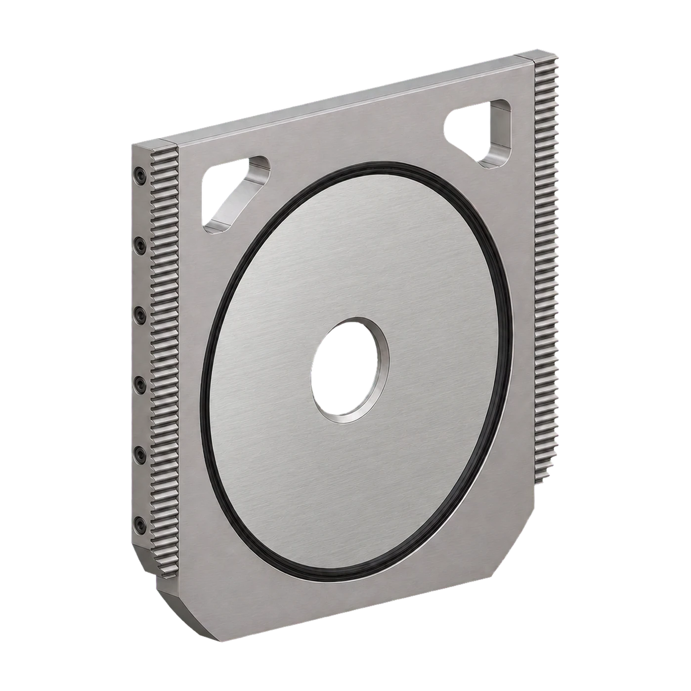
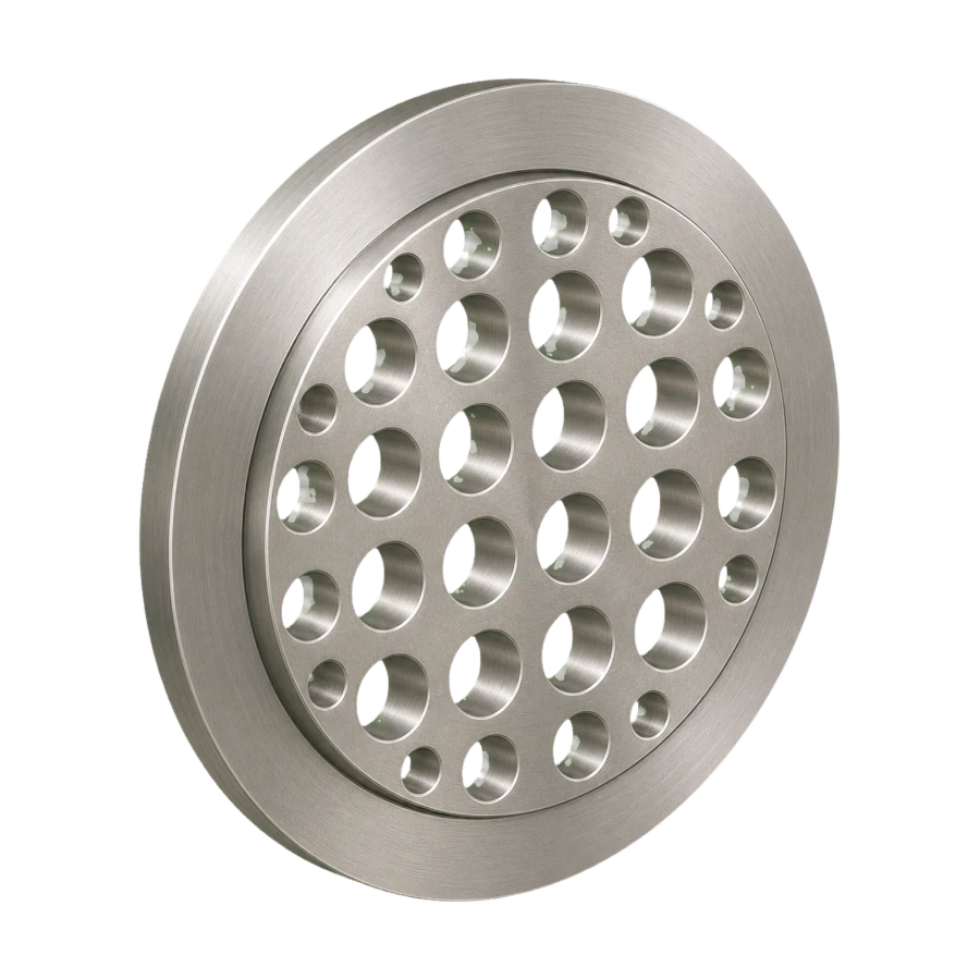
Level gauges & level tubes →Orifice Plate Holder (Plate Carrier)
Fits single and dual chamber fittings
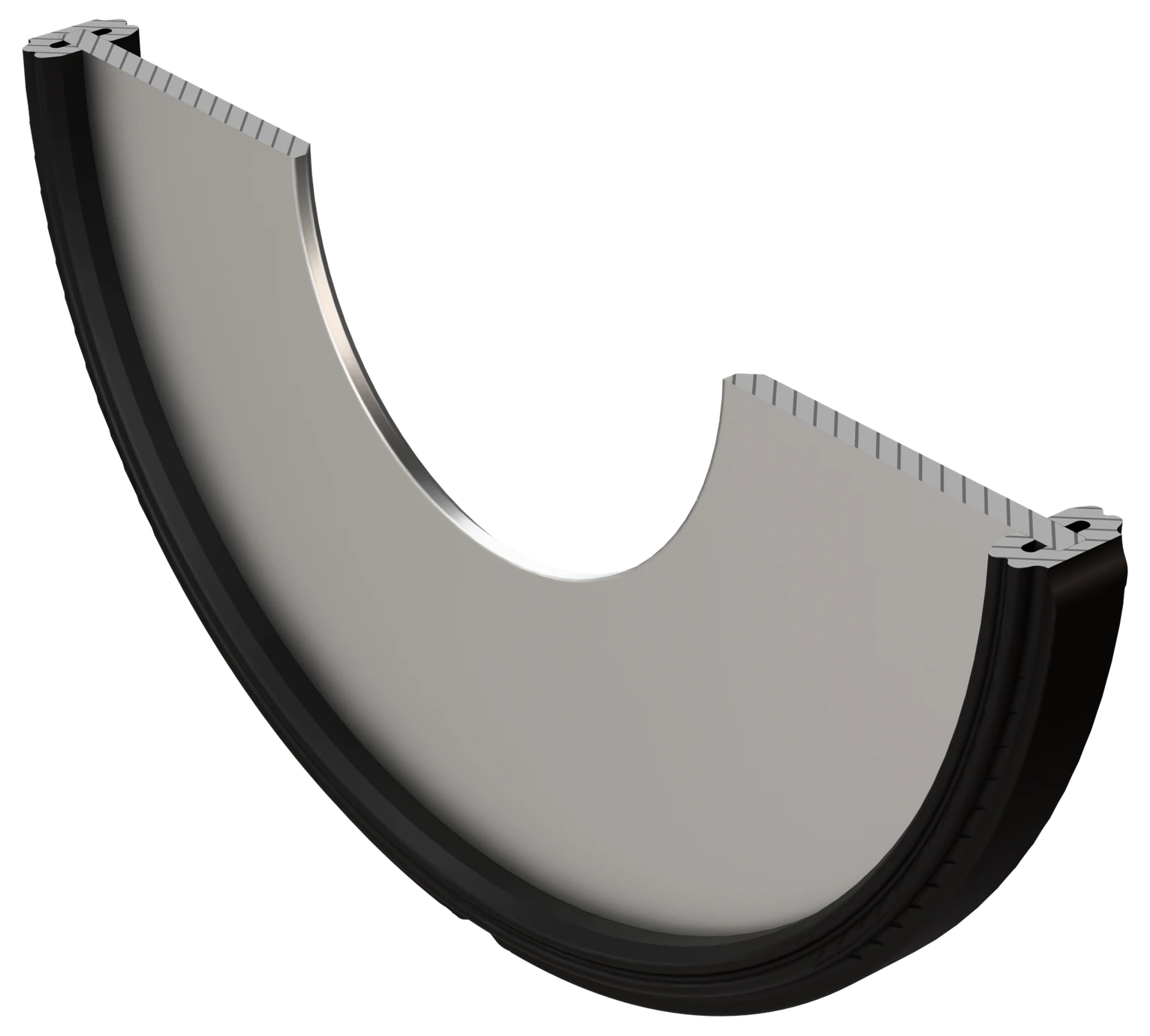
Carrier that holds the plate and its seal inside the fitting body, so the plate can be withdrawn through the chamber and re-seated square to the bore without disturbing the sealing faces. Machined to the fitting body and the plate outside diameter.
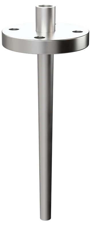
Thermowell
Bar stock or fabricated, to the specification
A closed-end well that carries the temperature sensor into the line, so the sensor can be withdrawn under line pressure. Drilled from bar stock or fabricated from tube; flanged, threaded or weld-in; checked by a wake frequency calculation to ASME PTC 19.3 TW.
Valve Manifold
For pressure and differential pressure transmitters
Two-, three- and five-valve manifolds that isolate the transmitter from the process and, on differential pressure service, equalise it for a zero check. Sourced to the project specification and supplied with the flow element.
Technical data
| Plate holder (carrier) fit | Machined to the fitting body and plate outside diameter |
| Seal arrangement | HNBR as standard; HNBR, FKM or PTFE-based seals for raw or sour gas; NBR only in clean sales gas |
| Condensate chamber volume | 0.5 – 5 litres, higher on request |
| Level tube centres | To vessel nozzle dimension |
| Pressure class | ASME Class 150 – 2500 as applicable |
| Plate holder (carrier) materials | 316L stainless steel as standard; 321, duplex (UNS S31803 / S32205), Alloy 400 (UNS N04400) or Alloy 625 (UNS N06625) on request |
| Marking | Tag number, job number, size and rating on each item; holder marked with the fitting it belongs to |
| Quality control | ISO 9001 system; PED where it applies; hydrostatic test on chambers and level tubes, or pneumatic where the project specifies; EN 10204 3.1 certificates, 3.2 on request |
| Documentation | Material certificate (EN 10204 3.1), dimensional report, pressure test record where applicable |
Material selection
Every accessory in this group is wetted, so each one is specified against the medium it sees and the line it is connected to.
Where it runs
Sectors this family is specified into most often.
Two accessories are drawn, one is calculated
The condensate chamber and the plate holder have a fixed envelope: the chamber follows the connection sizes and heights of the standard body, the holder follows the fitting bore and the plate outside diameter. Both are shown on a dimension drawing. The level tube has no standard envelope — it is built to the nozzle centres of the vessel.
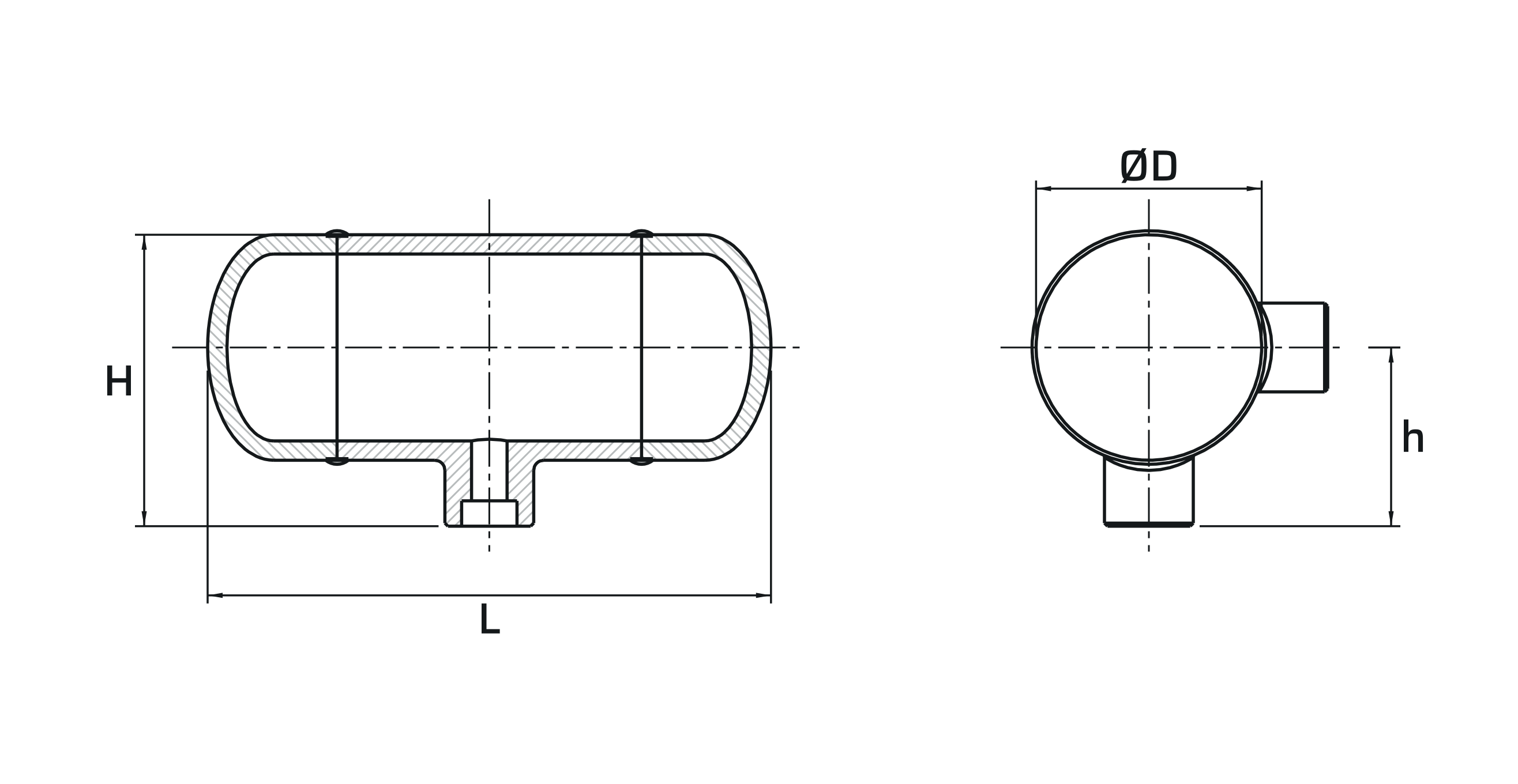
Condensate chamber
Body diameter, overall length and height, and the height of the side connection above the outlet face. Chamber volume and connection sizes are fixed per rating; the pair is supplied matched so both impulse legs sit at the same height.
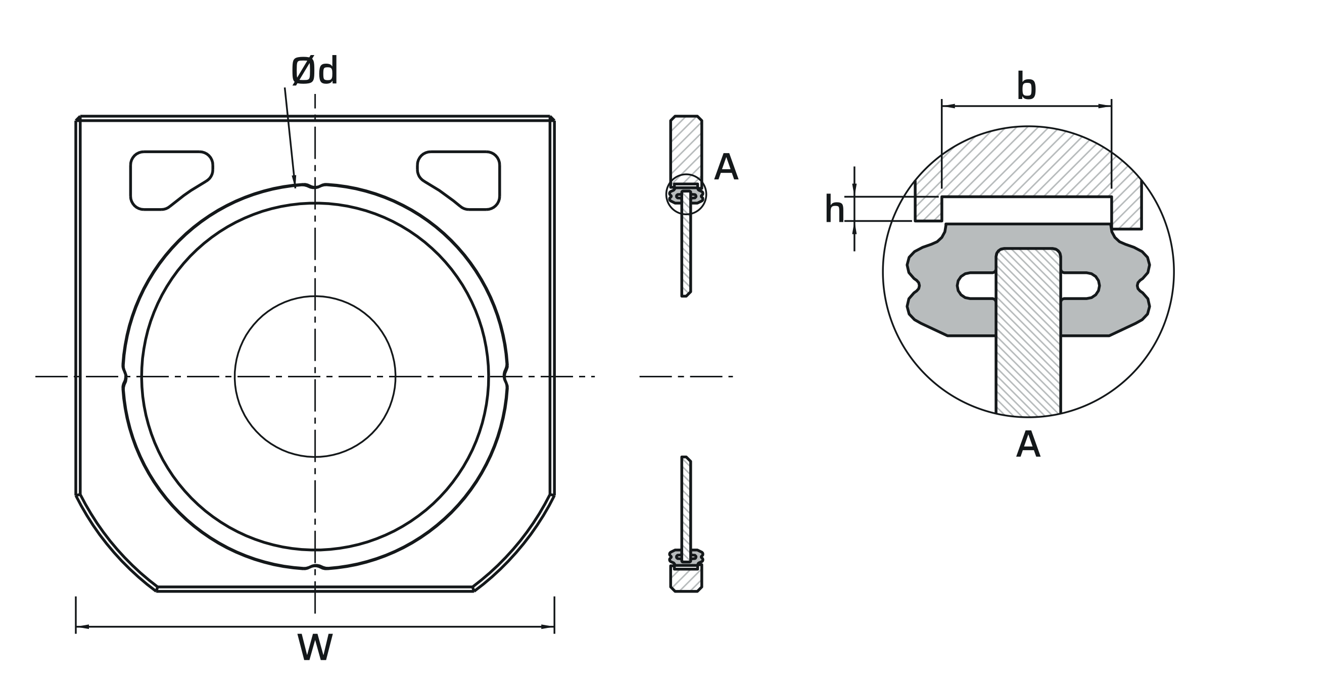
Orifice plate holder (carrier)
Holder bore, seal groove width and depth, and the width that matches the fitting body. Machined to the fitting it goes into and to the plate outside diameter, so both figures are needed with the order.
Level tube — what to send
A level tube is made to the vessel it hangs on. The centre-to-centre distance between the two nozzles is the figure that has to be right before anything is machined; everything else follows from it.
Send the same nozzle data for a condensate chamber pair if the impulse legs are already routed.
Sizing enquiry sheet →| What you send | What it decides |
|---|---|
| Nozzle centre-to-centre | Sets the tube length and the measuring span |
| Nozzle size, rating and facing | Fixes the end connections at both ends |
| Medium, pressure and temperature | Decides material, wall thickness and gasket |
| Vessel insulation thickness | Sets the stand-off between vessel wall and tube |
| Isolation and drain required | Valve arrangement at each connection and at the bottom |
| Tag numbers and quantity | Marking, and whether each tag has its own span |
Documents
- Condensate chamber: volume [0.5 – 5 litres], rating [ASME Class …].
- Level tube: centres to the vessel nozzle dimension [ … mm].
- Plate holder (carrier): machined to the fitting body and the plate outside diameter; material [316L] stainless steel ([321 / duplex / Alloy 400 / Alloy 625] where specified); seals [HNBR / FKM / PTFE-based] to the gas composition.
- Marking: tag number, size and rating on each item; plate holder marked with the fitting it belongs to.
- Testing: hydrostatic test on chambers and level tubes (pneumatic where specified).
- Documents: material certificate EN 10204 3.1 (3.2 where stated), dimensional report, pressure test record where applicable.
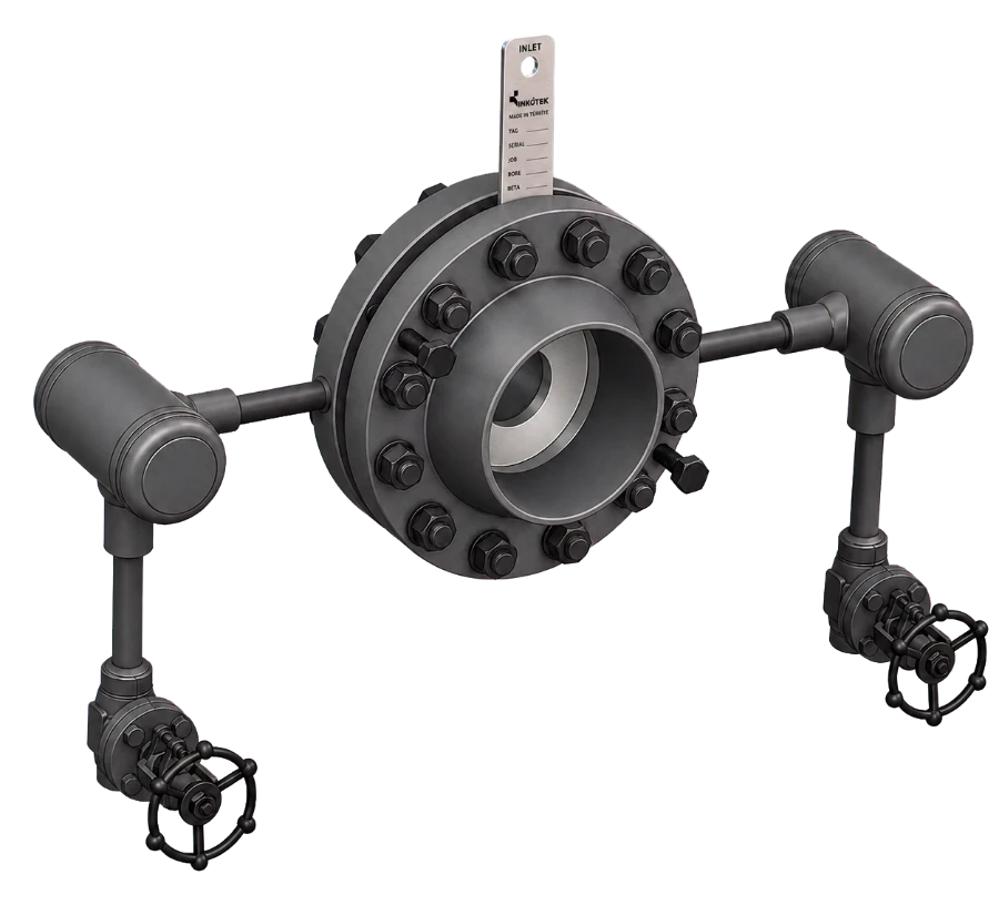
Process Accessories
Send the tag list with line size, insertion length, medium and the flow, pressure and temperature: a thermowell is checked by a wake frequency calculation. Accessories quoted alongside the flow elements arrive on the same delivery.