
Orifice Flange Union
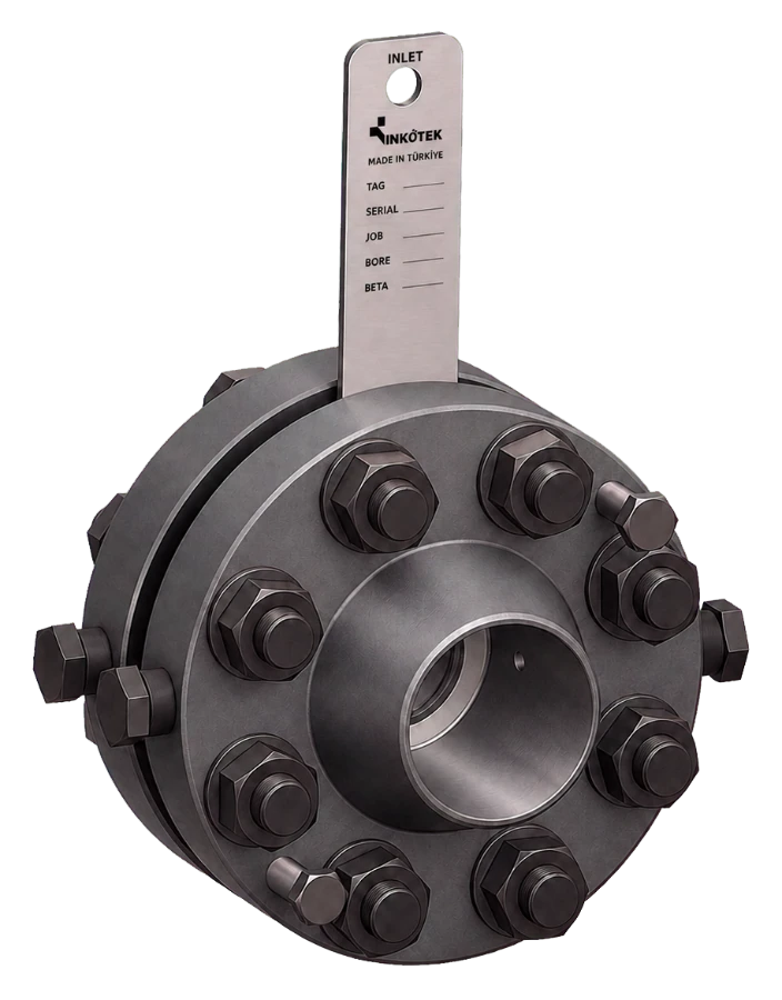
A plate held between a matched pair of orifice flanges with the pressure tappings drilled radially through the flanges. The most widely specified way to mount an orifice plate, and the reference case in ISO 5167-2. Supplied as a complete union — plate, both flanges, studs, nuts, jack screws and gaskets — so nothing has to be sourced separately on site.
Four build levels, one union
The difference between them is how much of the impulse line arrives already built. Each level adds parts that would otherwise be assembled in the field, where the tapping symmetry and the slope of the impulse legs are hardest to control.
Standard Union
Plate · flanges · fasteners
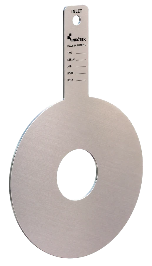
Plate with tab handle, matched flange pair, flange tappings, studs and nuts, jack screws and gaskets. Tappings plugged or prepared for the customer's impulse piping.
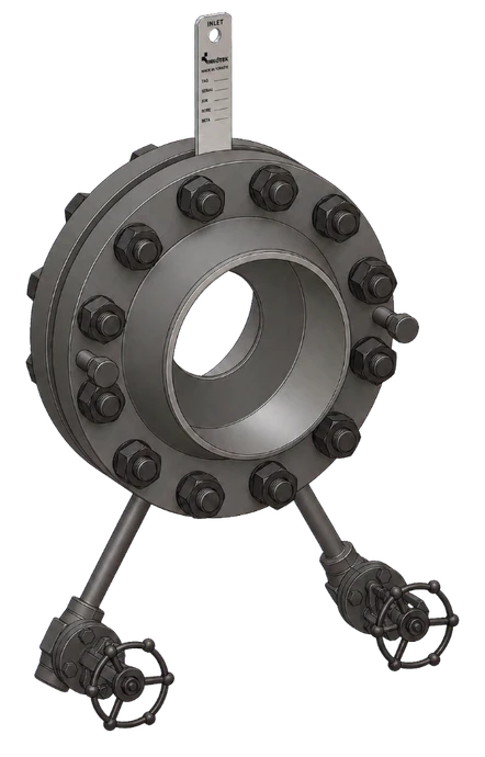
With Weld-On Shut-Off Valves
Root valves fitted
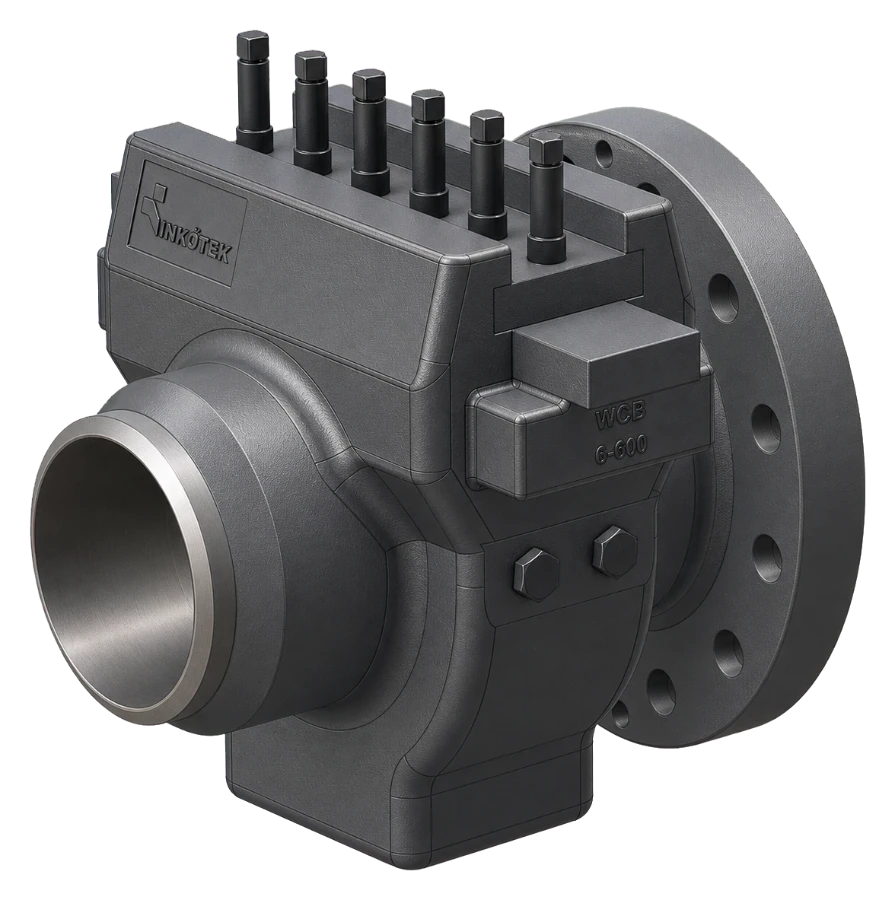
Welded pressure take-off nipples with one upstream and one downstream root valve, isolating the impulse lines without breaking into the flange tapping.
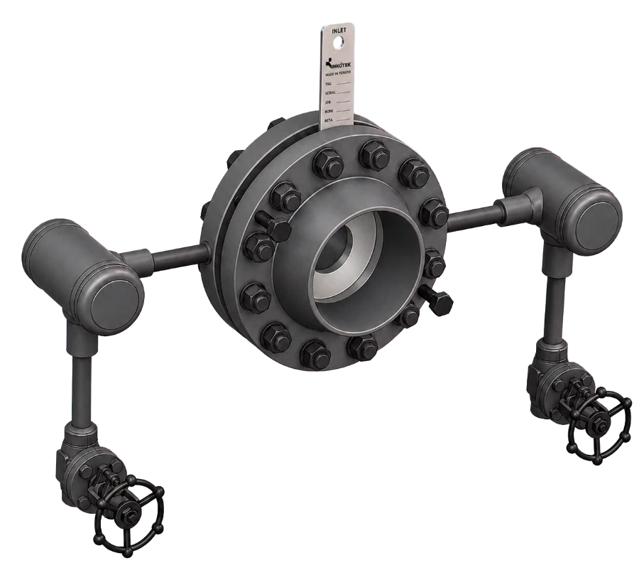
With Valves and Condensate Pots
Steam and condensing service
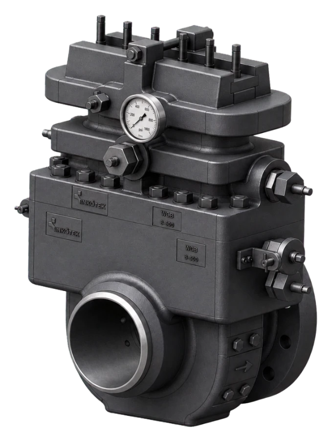
Two symmetrically positioned condensing chambers ahead of the root valves, keeping the impulse legs full and equal on steam and other condensing media.
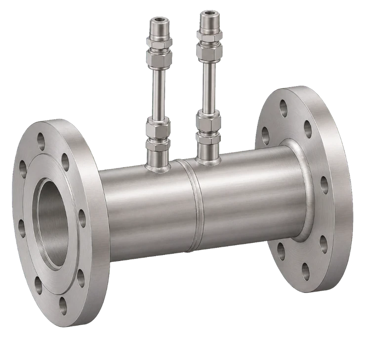
Orifice Flange Weldment
Supplied as one spool
The union welded into pipe sections and supplied as a single spool with flanged process ends. Arrives ready to drop into the line with no site welding at the tapping.
Technical data
| Size range | NPS 2″ – 24″ (DN 50 – DN 600), larger on request; below NPS 2″, a small bore meter run is supplied instead |
| Pressure class | ASME Class 150 – 600 standard; up to Class 2500 special production (Class 2500 up to NPS 12″); EN 1092-1 PN 6 – PN 400 |
| Flange standard | In most projects machined from ASME B16.5 flanges to the project's tapping detail; ASME B16.36 orifice flanges (Class 300 – 2500) where the standard detail suits the duty; EN 1092-1 on request |
| Facing | Raised face or ring type joint; flat face on request. On ASME B16.36 flanges, ring type joint from Class 600 |
| Tapping size | ½″ NPT standard; ¼″ and ¾″ available |
| Plate thickness | Per ISO 5167-2 against line size and differential pressure; AGA-3 where D < 50 mm |
| Bore designs | Concentric, eccentric, segmental, quadrant, conical entrance, multi-hole (conditioning) |
| Measuring uncertainty | Stated on the calculation sheet for the duty; discharge coefficient uncertainty to ISO 5167-2: 0.50 % at β 0.50, 0.75 % at β 0.75 |
| Permanent pressure loss | About 95 % of the differential at β 0.20, 73 % at β 0.50 and 45 % at β 0.75, falling as β rises (ISO 5167-2, 5.4.1) |
| Sealing surface | ASME B16.5 RF and RTJ facings, or EN 1092-1 facings to order |
| Marking | Plate: INLET, tag, serial and job numbers, bore, beta, material and heat number, marked on the upstream face (on the handle of paddle-type plates); rating and flow direction on the flange |
| Quality control | ISO 9001 system; PED where it applies; hydrostatic test, or pneumatic where the project specifies, on the orifice flange weldment; EN 10204 3.1 certificates, 3.2 on request |
| Documentation | Sizing calculation, material certificate (EN 10204 3.1), dimensional report |
Material selection
The plate is chosen for the medium, the flanges for the piping class. Temperature decides which end of the carbon and alloy range applies.
Where it runs
Sectors this family is specified into most often.
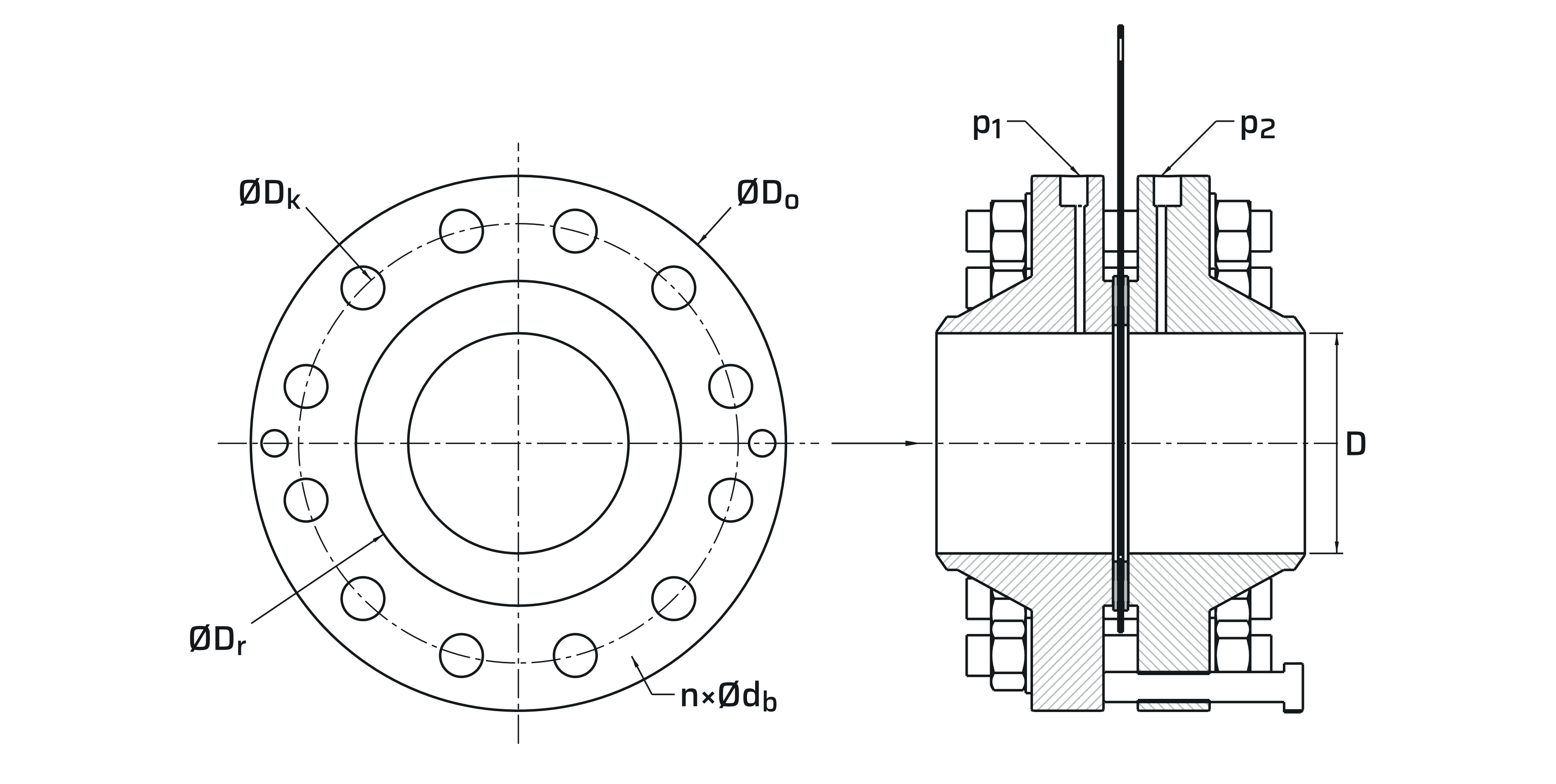
Dimension drawing
Flange outside diameter, bolt circle, bolt hole count and raised face diameter follow ASME B16.5, or ASME B16.36 where its standard tapping detail is used, for the class you specify. The plate thickness follows ISO 5167-2, or AGA-3 where D < 50 mm; the tappings follow ISO 5167-2 where the tap hole stays below 0.13D and 13 mm (5.2.2.7), otherwise AGA-3. Both are confirmed on the dimensional report shipped with the union.
Documents
- Primary element: orifice plate between a pair of orifice flanges with flange tappings; line size [NPS …], rating [ASME Class … / PN …].
- Flanges: [ASME B16.5 flanges machined to the tapping detail / ASME B16.36 orifice flanges / EN 1092-1], [RF / RTJ] facing.
- Tappings: [½″ NPT / ¼″ NPT / ¾″ NPT], drilled radially through each flange; to ISO 5167-2 where the tap hole stays below 0.13D and 13 mm, otherwise AGA-3.
- Plate: [concentric] bore; thickness to ISO 5167-2 against line size and differential pressure, AGA-3 where D < 50 mm; material [316L] stainless steel. Flanges to the line piping class [ … ].
- Marking: plate INLET, tag, serial number, bore, β, material and heat number on the upstream face (on the handle of paddle-type plates); rating and flow direction on the flange.
- Testing and documents: hydrostatic test of the orifice flange weldment (pneumatic where specified); sizing calculation, material certificate EN 10204 3.1 (3.2 where stated), dimensional report.
Orifice Flange Union
Send the line size, class, facing and the medium. We come back with a sized plate, the union bill of material and a price — usually within two working days.