
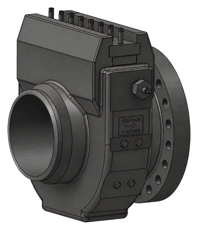
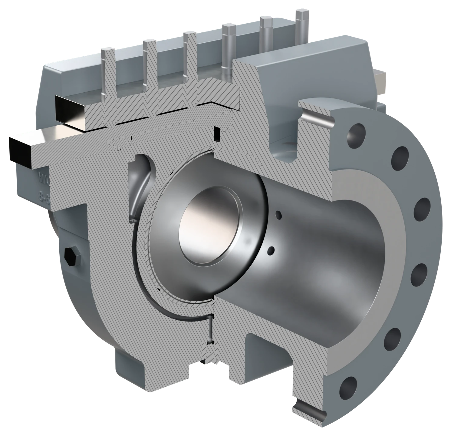
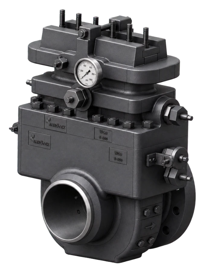
Single Chamber Orifice Fitting
One plate-holding and service chamber. Raising the plate is a single operation with far fewer parts than a dual chamber body, which keeps the overall height lower and the fitting lighter and cheaper — at the cost of isolating and depressurising the section before the plate comes out.
Two internal arrangements, chosen by line size
Below NPS 12″ the plate sits in a carrier screwed under the seal bar and lifts out with it by hand. Above it, the plate and its carrier need a gear to come out cleanly — so the internal arrangement changes.
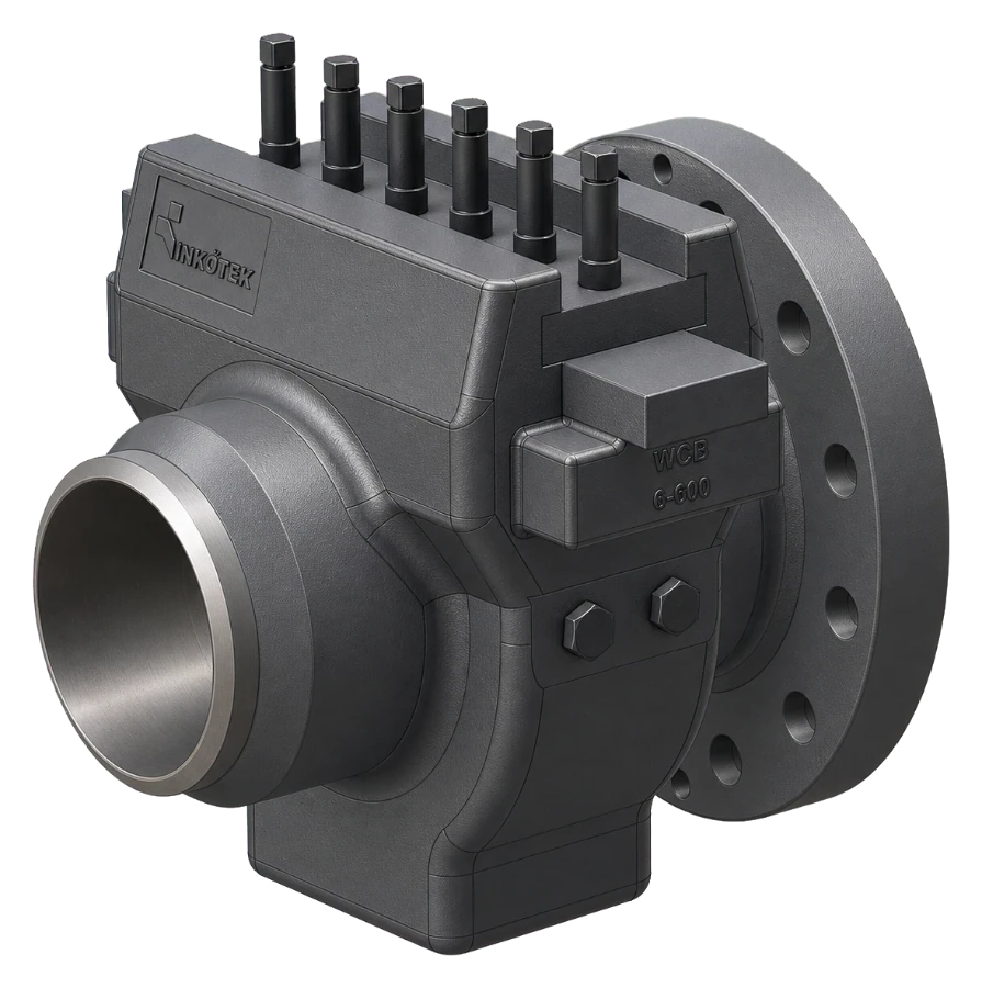
Carrier under the seal bar
The plate sits in a carrier screwed under the seal bar, and the clamp bar presses the unit onto the body. There is no pinion gear mechanism in the chamber.
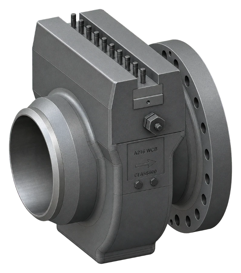
Plate carrier with pinion gear
The plate sits in a separate plate carrier, raised out of the bore by a pinion gear, so the gear takes the weight of a large plate.
The single chamber fitting in 36 seconds
One plate-holding chamber: the clamp bar presses the seal bar, plate carrier and orifice plate onto the body seat; the HNBR plate seal; flange tappings 25.4 mm from each plate face; plate access from the top once the line section is isolated and depressurised, and the plate lifted out by hand — no pinion gear up to NPS 10″, a pinion gear from NPS 12″.
36 s · no sound
Technical data
Standard manufacturing range. Outside these limits, ask us — the range is set mostly by machining capacity, not by design.
| Type | Single chamber fitting; weld × flange standard, flange × flange or weld × weld on request |
| Line size | DN 50 – DN 600 (2″ – 24″) standard; up to DN 1000 (40″) special production |
| Pressure rating | ASME Class 150 – 600 standard; special production up to Class 2500 for NPS 2″ – 12″ and up to Class 1500 for NPS 14″ – 24″ |
| Design standard | ISO 5167-1 / ISO 5167-2 plate basis; AGA Report No. 3 where specified and where ISO 5167-2 does not apply. Flanged ends to ASME B16.5 (B16.47 above NPS 24″), RF or RTJ; butt weld ends to ASME B16.25 |
| Pressure tappings | Flange tappings integral to the fitting body |
| Plate access | From the top, once the line section is isolated and depressurised and the clamp bar is removed |
| Seal options | HNBR as standard; HNBR, FKM or PTFE-based seals for raw or sour gas; NBR only in clean sales gas |
| Marking | Nameplate with model, size and serial number; flow direction on the body; tag number and bore per project |
| Plate handling | NPS 2″ – 10″: plate in a carrier screwed under the seal bar, pressed onto the body by the clamp bar; NPS 12″ and above: separate plate carrier raised by a pinion gear |
| Options | Drain connections, painted body or electroless nickel plating |
| Measuring uncertainty | Set by β, the Reynolds number and the installation; stated on the calculation sheet for the duty; discharge coefficient uncertainty to ISO 5167-2: 0.50 % at β 0.50, 0.75 % at β 0.75 |
| Permanent pressure loss | About 95 % of the differential at β 0.20, 73 % at β 0.50 and 45 % at β 0.75, falling as β rises (ISO 5167-2, 5.4.1) |
| Quality control | ISO 9001 system; PED where it applies; hydrostatic test, or pneumatic where the project specifies; leak test to the project ITP; factory function test; EN 10204 3.1 certificates, 3.2 on request |
| Documentation | Sizing calculation, material certificate (EN 10204 3.1), dimensional report and specified pressure-part records |
| Notes | Line size — built to ISO 5167, the tap holes are 4, 5, 6, 8, 10 or 12 mm by line size, inside the ISO 5167-2 limit (5.2.2.7). With AGA-3 tap holes, NPS 2″, NPS 3″ Sch 160 and heavier and NPS 4″ Sch 80 and heavier exceed that limit and are built to AGA-3; NPS 2″ Sch 80 and heavier is below D = 50 mm (5.3.1) and is built to AGA-3 in any case. |
Materials
The body and its end connections are one casting, so one grade covers both. Low temperature grades are specified where the minimum design temperature, including Joule–Thomson cooling at the station, calls for them. Apart from any AISI 431 parts, the standard materials are selected for sour service. Where sour service is specified, those parts change to 17-4PH, double aged (H1150D); additional tests such as hardness testing are carried out and the documentation is prepared to NACE MR0175 / ISO 15156.
Applications
Sectors this family is specified into most often.
Dimension drawings
Body length follows the end connection standard and the pressure rating. Allow the stated headroom above the fitting so the plate can be lifted clear of the bore.
The internal arrangement changes with size, so the family is drawn as two bands. Both share the same symbols.
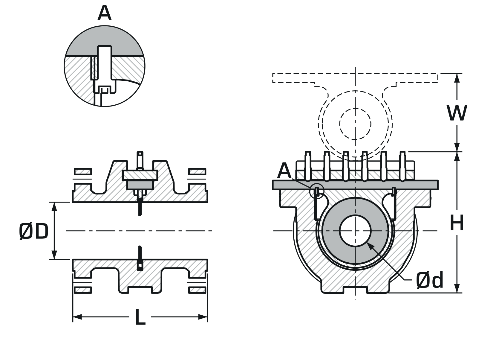
NPS 2″ – 10″
Carrier under the seal bar
The plate sits in a carrier screwed under the seal bar, and the clamp bar presses the unit onto the body seat. Fewer parts, lower overall height, and the shortest headroom of the two bands.
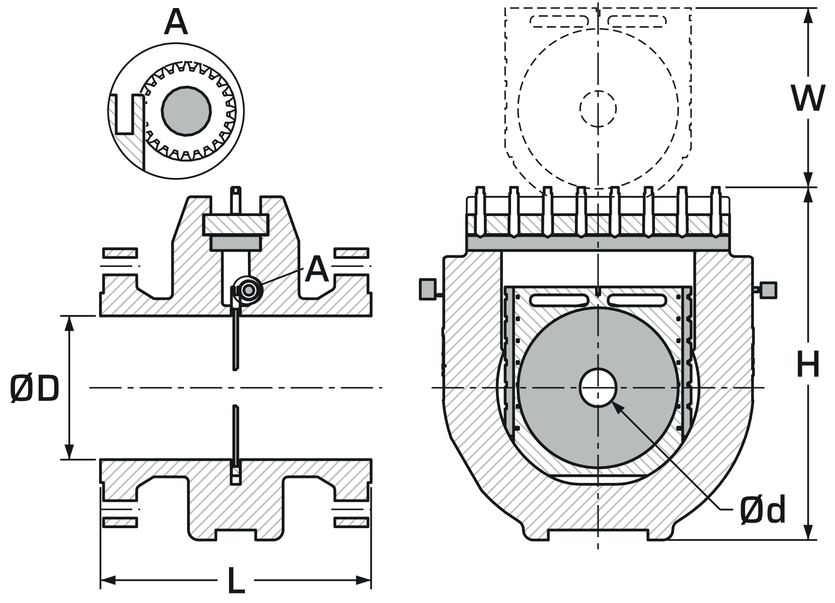
NPS 12″ and above
Plate carrier with pinion gear
The plate sits in a separate plate carrier that a pinion gear raises out of the bore. Overall height and headroom grow with the carrier travel.
Weld × flange dimensions
| NPS | Class | Weld end × flange face | L | C | H | W |
|---|---|---|---|---|---|---|
| 2″ | 600 | Sch 160 × RTJ | 264 | 136 | 283 | 67 |
| 4″ | 600 | Sch 80 × RF | 333 | 167 | 339 | 129 |
| 4″ | 600 | Sch 80 × RTJ | 335 | 169 | 339 | 129 |
| 6″ | 600 | Sch 80 × RF | 399 | 203 | 413 | 187 |
| 8″ | 600 | Sch 80 × RF | 453 | 227 | 477 | 264 |
| 12″ | 600 | Sch 80 × RF | 488 | 272 | 709 | 360 |
| 16″ | 600 | Sch 80 × RF | 642 | 346 | 775 | 433 |
Dimensions in mm. L: weld end to flange face. C: plate centre to flange face. Flange × flange and weld × weld lengths, other sizes and classes on the approved drawing. Source: INK-DS-02.
Documents
- Primary element: single chamber orifice fitting; the plate is lifted out from the top once the line section is isolated and depressurised; line size [NPS …], rating [ASME Class …].
- Design: plate to ISO 5167-1 / ISO 5167-2; AGA Report No. 3 where specified and where ISO 5167-2 does not apply.
- End connections: [weld × flange / flange × flange / weld × weld], integral with the body casting; flanged ends to ASME B16.5 (B16.47 above NPS 24″), [RF / RTJ]; butt weld ends to ASME B16.25.
- Pressure tappings: flange tappings integral to the fitting body.
- Materials: body [A216 WCB / LCB-equivalent cast steel for low temperature service]; plate [316L] stainless steel; seals [HNBR / FKM / PTFE-based] to the gas composition; sour service to NACE MR0175 / ISO 15156 where stated.
- Marking: nameplate with model, size and serial number; flow direction on the body; tag number and bore.
- Testing and documents: hydrostatic test (pneumatic where specified), leak test to the project ITP and factory function test; sizing calculation, material certificate EN 10204 3.1 (3.2 where stated), dimensional report and pressure-part records.
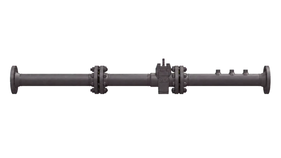
Single Chamber Orifice Fitting
Send the pipe size, flow rate, pressure, temperature and medium. We come back with a sized fitting, a calculation sheet and a price — usually within two working days.