
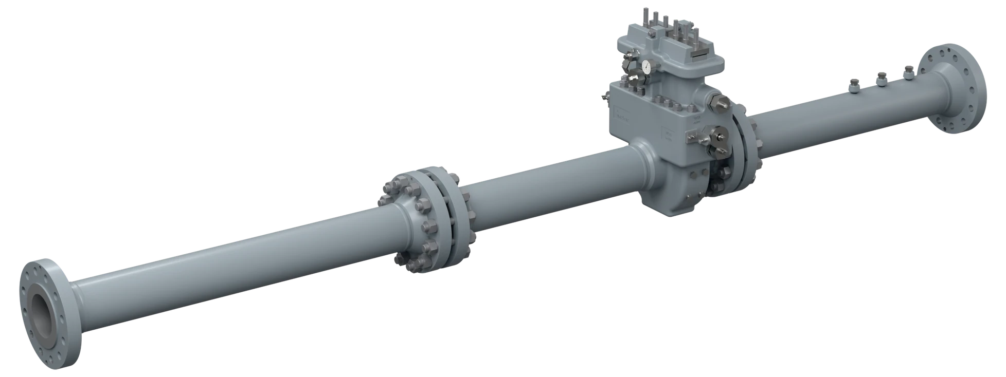
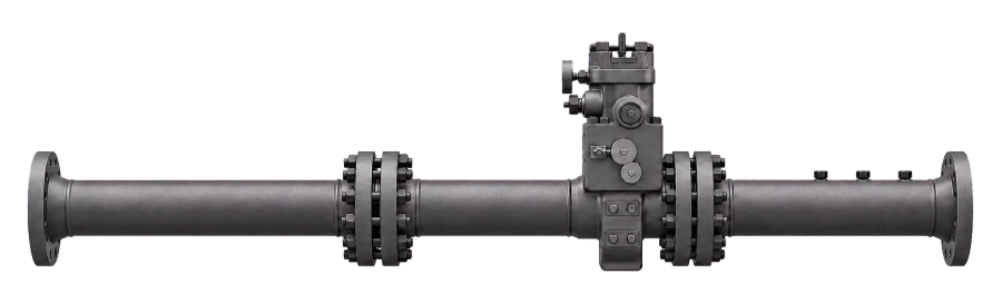
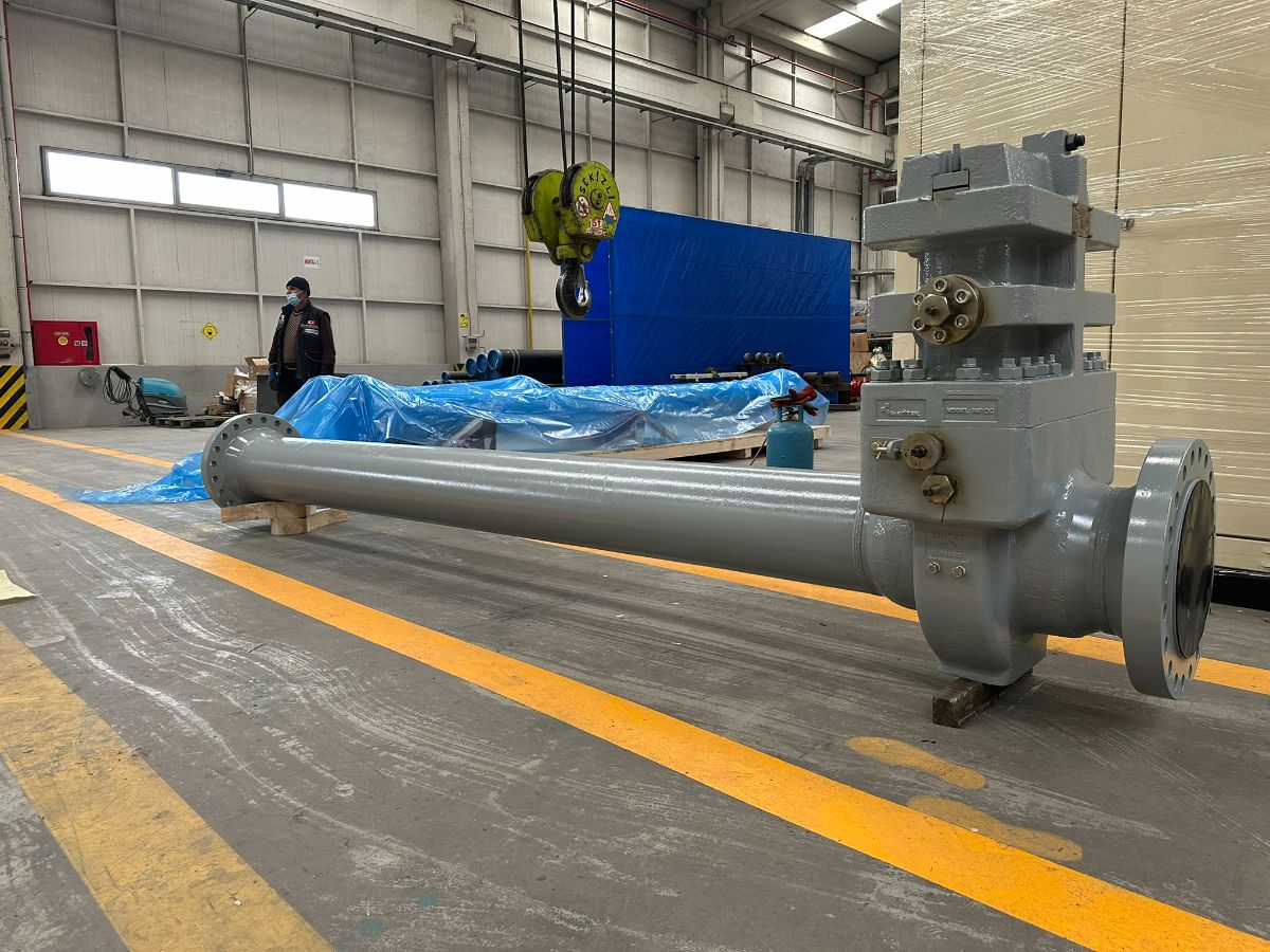
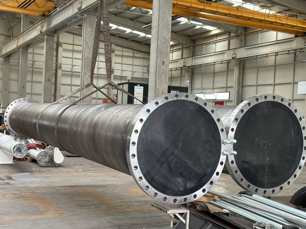
Custody Transfer Meter Runs
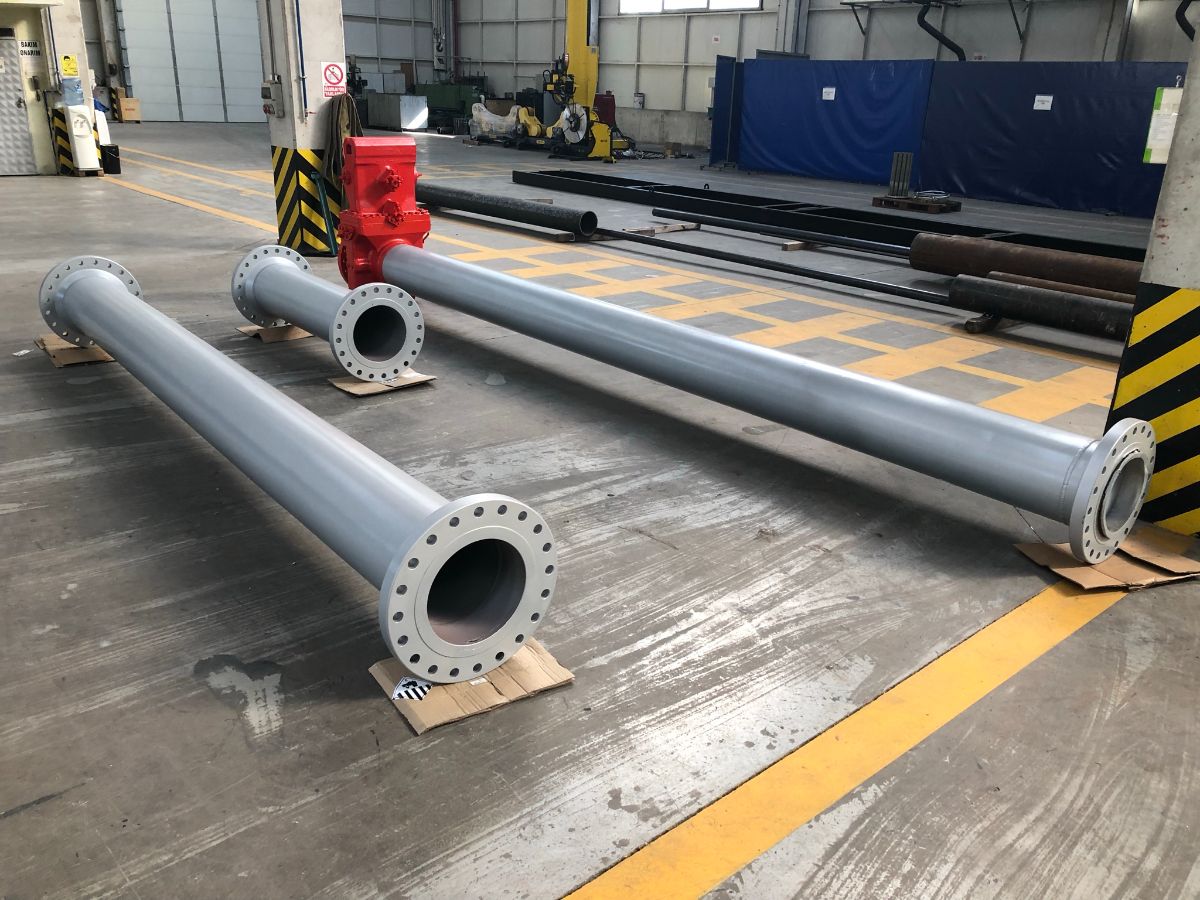
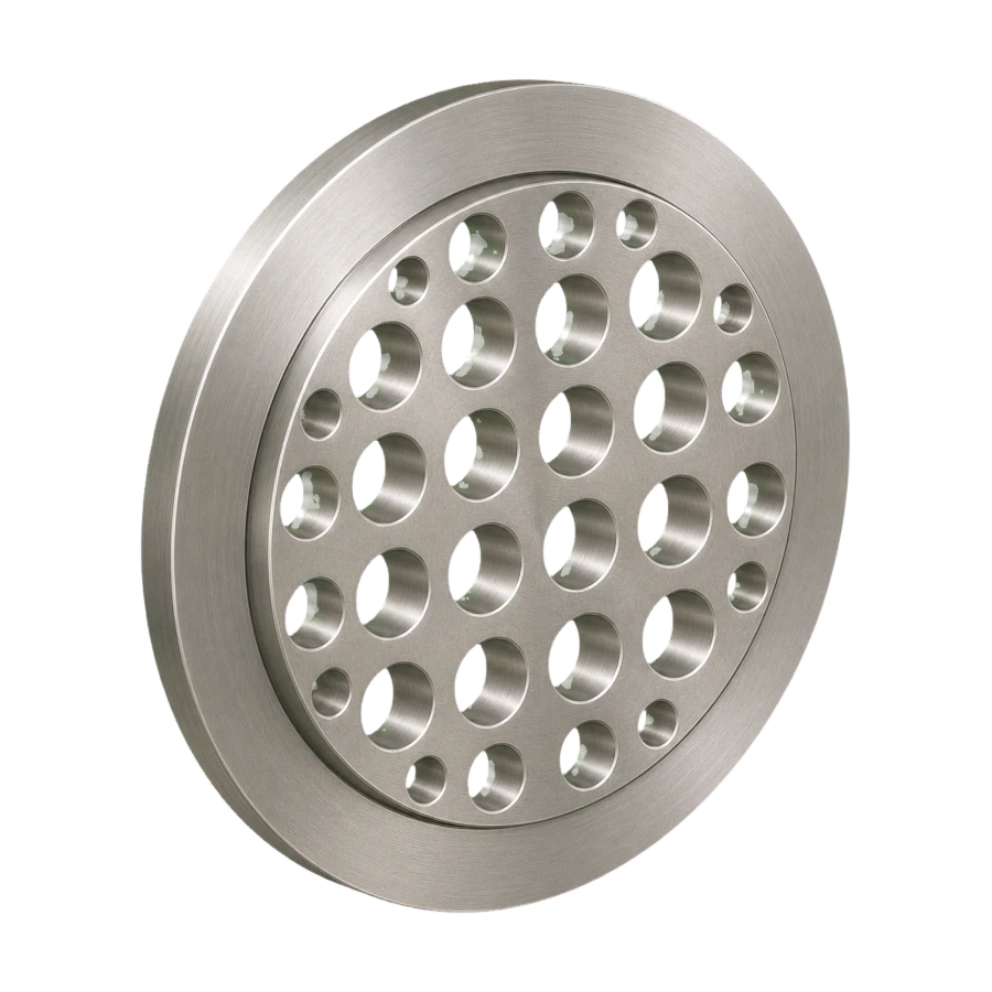
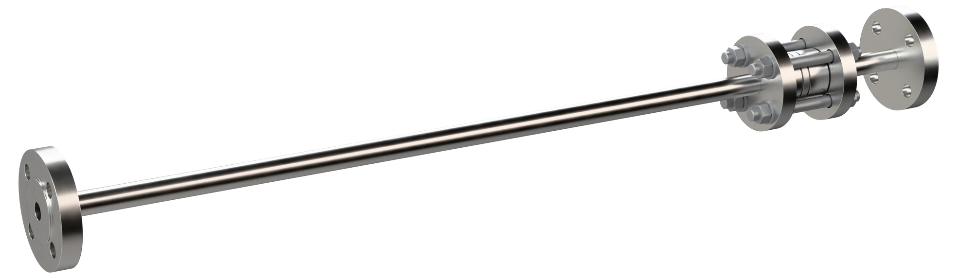
A complete measurement spool built and documented as one item: upstream straight length, flow conditioning, the primary element, downstream length and matched flanged ends. The straight run is machined and verified in the shop rather than assumed on site, which is where most installed uncertainty is lost.
The primary element is a choice inside the run
All three runs are built the same way. What changes is how the plate is held — and that decides whether a plate change needs a shutdown, a local outage, or nothing at all.
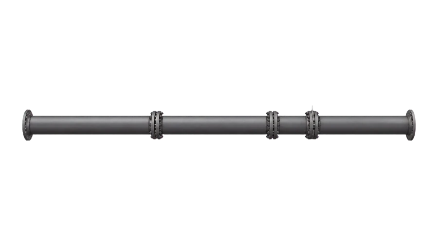
Orifice Plate Meter Run
Plate between orifice flanges
Plate mounted between orifice flanges with inlet and outlet spools welded either side. No moving parts in the run. A plate change means shutting down and breaking the flange.
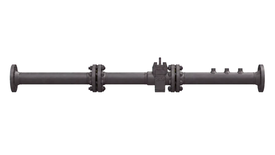
Single Chamber Fitting Run
Local outage to change a plate
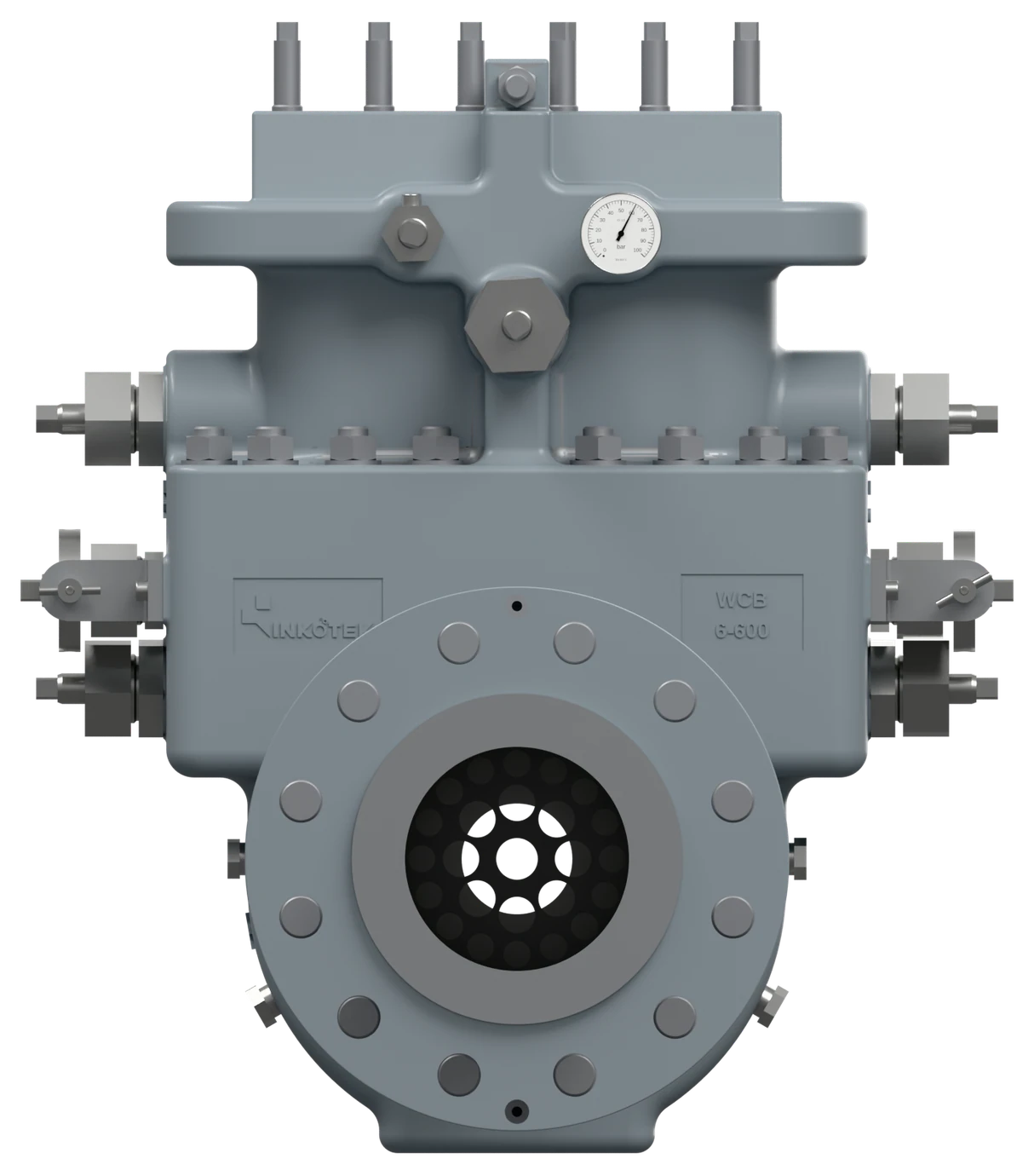
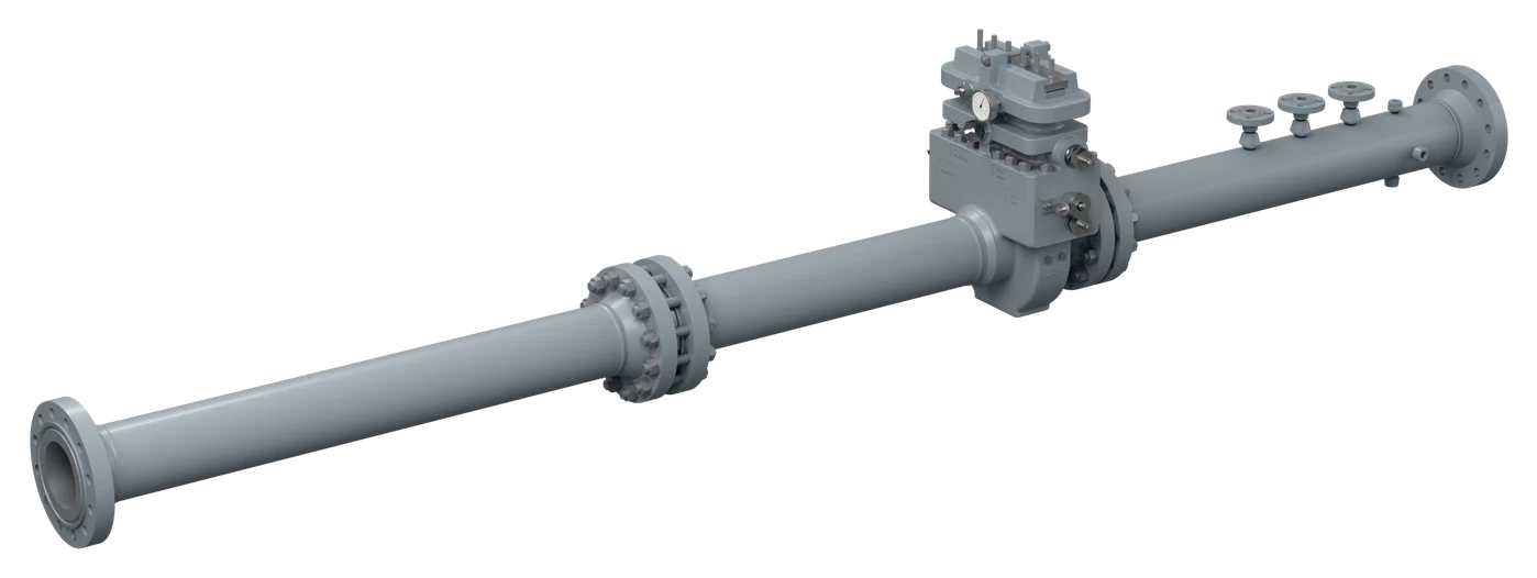
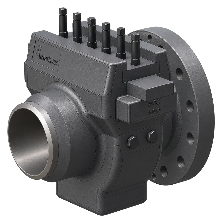
Single chamber fitting welded into a complete run with conditioning and matched pipe sections. The plate comes out through the top once the line section is isolated and depressurised and the clamp bar is removed.
Dual Chamber Fitting Run
Plate change under pressure
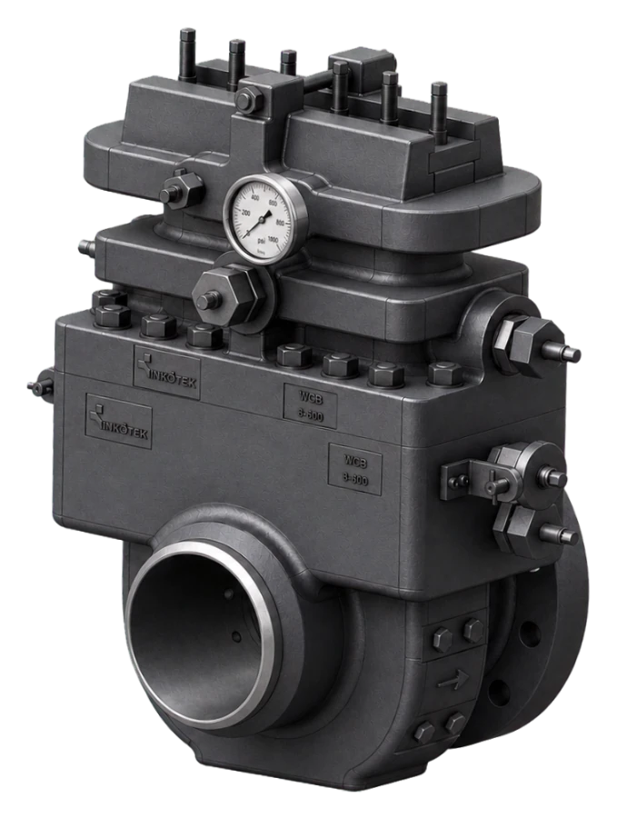
Dual chamber fitting welded into the run, keeping plate access live. The line stays in service at full pressure while the plate is withdrawn through the upper chamber.
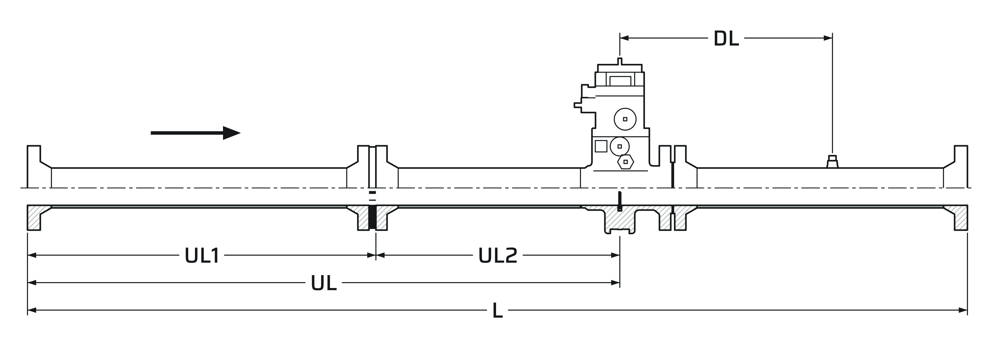
Where the straight lengths are measured
Upstream and downstream lengths meet at the orifice plate. The conditioner divides the upstream length into UL1 and UL2; the downstream length DL runs to the thermowell. The values follow from the beta ratio and are stated on the calculation sheet for the duty.
Technical data
| Size range | Orifice plate meter run NPS 2″ – 44″ (DN 50 – DN 1100); dual and single chamber fitting runs NPS 2″ – 24″ (DN 50 – DN 600), higher sizes on request |
| Pressure class | ASME Class 150 – 600 standard; up to Class 2500 special production to NPS 12″; fitting runs NPS 14″ – 24″ up to Class 1500 |
| Design codes | AGA Report No. 3, ISO 5167-1 and -2 |
| Straight lengths | Per AGA-3 / ISO 5167-2, or shortened with a conditioner |
| Flow conditioning | Zanker, NEL (Spearman), Laws, tube bundle |
| Tube bore tolerance | Machined and recorded; four diameters measured in each cross-section |
| End connections | Flanged to ASME B16.5 / B16.47 with RF, RTJ or groove type facing; butt weld ends to ASME B16.25; special end connections on request |
| Measuring uncertainty | Set by the element in the run and by compliance with the straight-run and bore requirements; stated on the calculation sheet for the duty |
| Internal surface finish | Bore honed or machined to the roughness the standard requires for the line size and beta ratio in use, inside both its upper and lower limits |
| Marking | Tag number, job number, measured bore, flow direction and spool identification on each section |
| Quality control | ISO 9001 system; PED where it applies; qualified welding procedures, NDE and a hydrostatic test (pneumatic where the project specifies) to the project specification |
| Documentation | Sizing calculation, bore measurement report, material certificates (EN 10204 3.1/3.2), welding and NDE records |
| Notes | Size range — ISO 5167-2 covers bores from 50 mm to 1000 mm (5.3.1): larger runs and NPS 2″ Sch 80 and heavier (D < 50 mm) are built to AGA-3. Flange and D and D/2 tap holes on runs built to ISO 5167 are 4 – 12 mm by line size, inside its limit (5.2.2.7); with AGA-3 tap holes, NPS 2″, NPS 3″ Sch 160 and heavier and NPS 4″ Sch 80 and heavier fitting runs are built to AGA-3 (INK-DS-02). |
Material selection
A custody transfer run is qualified as one package, so every pressure part is specified to the same minimum design temperature and rating.
Where it runs
Sectors this family is specified into most often.
What to send for sizing
A meter run has no catalogue length. Upstream and downstream lengths come out of the beta ratio and the fittings ahead of the run, per AGA-3 and ISO 5167-2; where the available space is shorter than the standard demands, a conditioner is placed at the qualified distance and the run is built around it.
The general arrangement, with support spacing and centreline height, is issued for approval before fabrication starts.
Sizing enquiry sheet →| Process data | What it decides |
|---|---|
| Line size, schedule and material | Sets the spool bore and the material of the whole run |
| Flange standard, rating and facing | Raised face or RTJ, and the end preparation if welded in |
| Element required in the run | Flange union, single chamber or dual chamber fitting |
| Medium, flow range, pressure and temperature | Sets β, the bore and the differential at each flow point |
| Overall length available | Decides whether a conditioner is needed to meet the straight-run rule |
| Upstream fittings and layout | Bends, valves and reducers each carry their own length requirement |
| Fiscal or custody transfer duty? | Decides whether AGA-3 applies alongside ISO 5167 |
| Witnessed inspection required? | Sets the test and documentation scope, and the delivery time |
Documents
- Meter run: [orifice plate / dual chamber fitting / single chamber fitting] meter run to AGA Report No. 3 / ISO 5167-1 and -2; line size [NPS …], rating [ASME Class …].
- Straight lengths: to AGA-3 / ISO 5167-2, or shortened with a [Zanker / NEL (Spearman) / Laws / tube bundle] flow conditioner at its qualified position.
- Tube bore: machined and recorded, four diameters measured in each cross-section; internal surface within the upper and lower roughness limits of the standard for the line size and β.
- End connections: flanged to ASME B16.5 / B16.47, [RF / RTJ]; or butt weld ends to ASME B16.25.
- Materials: [ … ], to suit the process and the line piping class.
- Marking: tag number, measured bore, flow direction and spool identification on each section.
- Fabrication, testing and documents: qualified welding procedures, NDE and hydrostatic test (pneumatic where specified) to the project specification; sizing calculation, bore measurement report, material certificates EN 10204 3.1 / 3.2, welding and NDE records.
Custody Transfer Meter Runs
Send the line size, the flow range and how much straight pipe you actually have. We come back with a run layout, the conditioning arrangement it needs and a price.