
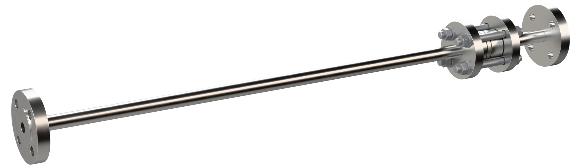
Small Bore Meter Run
An orifice element combined with controlled upstream and downstream meter-run sections, designed to ASME MFC-14M. The bore, the alignment and the tapping positions are set in the workshop rather than in the field — which is where small-line measurements usually go wrong.
Two constructions, chosen by how the run is maintained
The measurement is the same. The difference is whether the element comes apart in the field or the run is supplied as one permanent section.
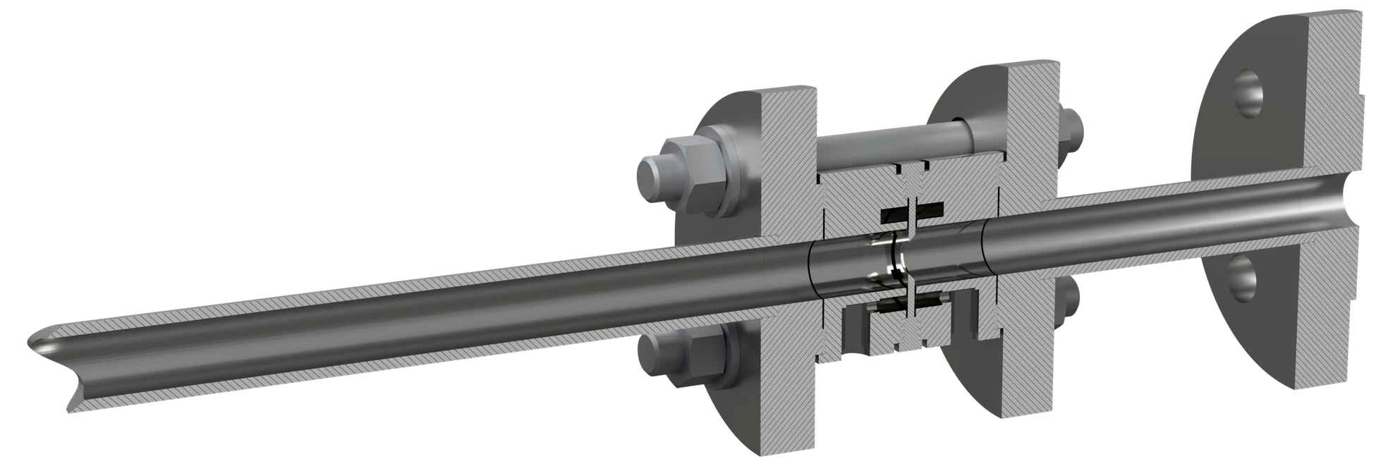
Flange-mounted annular chamber type
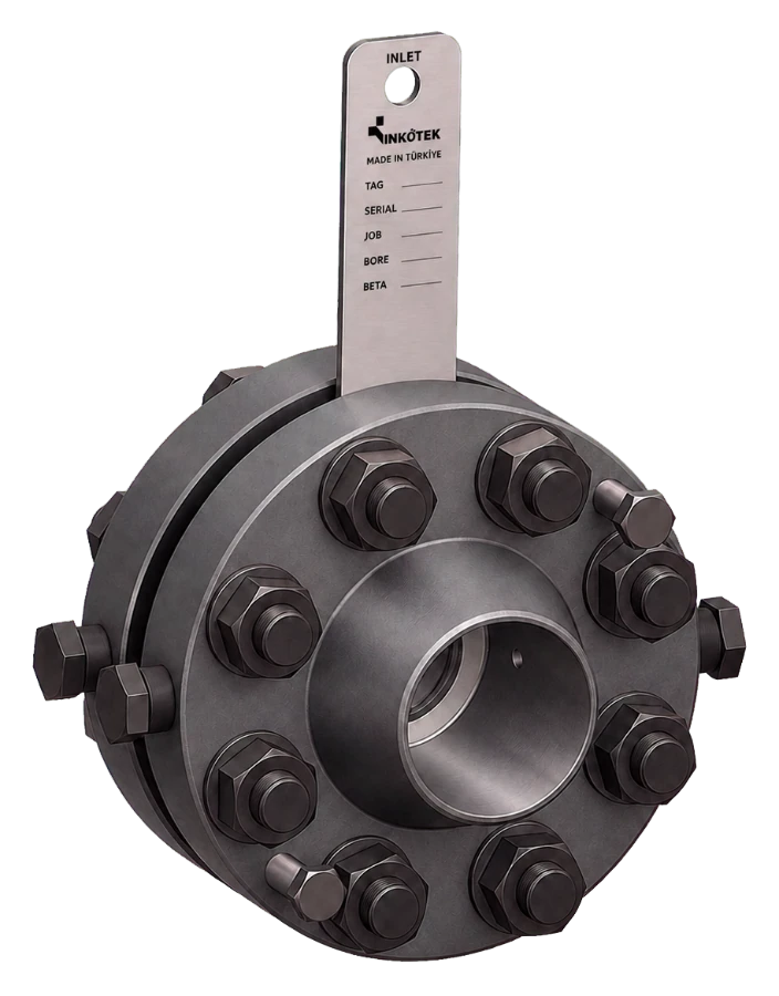
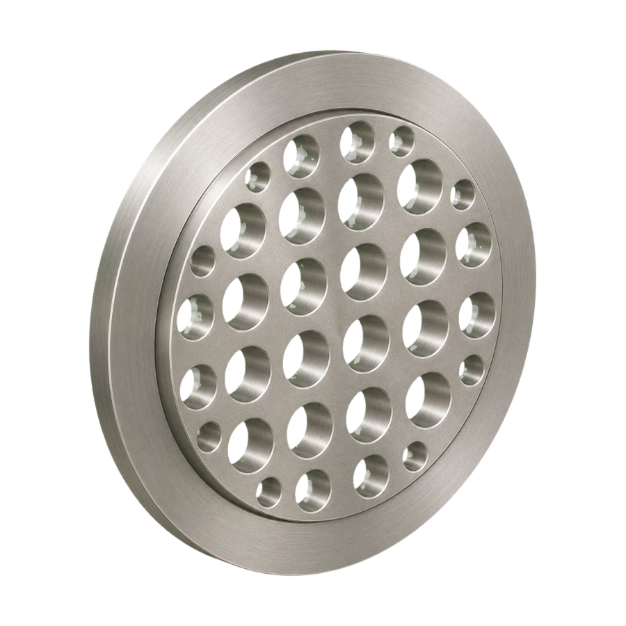
The element is installed between mating flanges with annular pressure chambers or carrier rings around the bore, and precisely positioned upstream and downstream tappings.
Welded meter run type
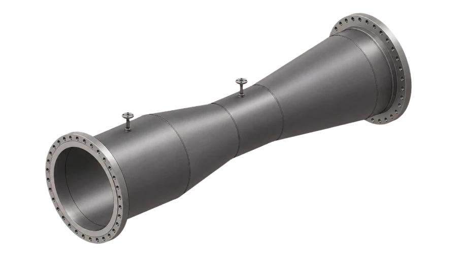
The element is integrated into a welded meter-run assembly with precision-bore pipe sections and a permanently integrated pressure-tapping structure.
Technical data
Standard manufacturing range. Outside these limits, ask us — the range is set mostly by machining capacity, not by design.
| Construction | Removable: orifice ring with annular tappings between two opposing ASME B16.5 or EN 1092-1 flanges; permanent: welded meter run |
| Line size | NPS ½″ – 1½″ (DN 15 – DN 40), sized to your service data |
| Pressure rating | ASME Class 150 – 600 standard; up to Class 2500 special production; EN 1092-1 PN 6 – PN 400 |
| Design standard | ASME MFC-14M — meter tube, orifice plate, tapping positions and straight lengths |
| Pressure tappings | Corner taps through an annular slot into an annular chamber or carrier ring, or flange taps 25.4 mm from each plate face |
| Bore control | Meter tube circular and cylindrical within ± 0.025 mm, roughness below 0.25 µm (ASME MFC-14M, 6.2.2, 6.2.4) |
| Options | Butt-weld, flanged or mixed process ends; drain and vent connections outside the meter tube |
| Measuring uncertainty | Stated on the calculation sheet for the duty; it depends on the bore ratio and on the run being built to the straight lengths the standard requires |
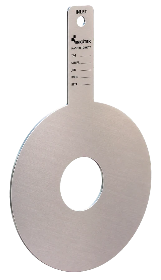
| Marking | Tag number, bore d, meter tube D at 20 °C, beta and flow direction, marked on the body |
| Quality control | ISO 9001 system; PED where it applies; qualified welding procedures, NDE and a hydrostatic test (pneumatic where the project specifies) to the project specification |
| Documentation | Sizing calculation, material certificate (EN 10204 3.1), dimensional report |
| Notes | Pressure tappings — flange taps are calculated for NPS 1″ – 1½″ only and flow calibrated below NPS 1″ (ASME MFC-14M 7.2); a welded run with other tapping geometry is flow calibrated. Bore control — honed only where the tube as supplied does not meet these limits; internal bore (four diameters measured in each cross-section) and alignment recorded on the dimensional report. |
Materials
The run is delivered as one assembly, so the tube, the flanges and the fitting are specified to a single temperature rating and a single piping class.
Applications
Sectors this family is specified into most often.
What to send for sizing
Overall length comes out of the meter tube ASME MFC-14M requires — at least 18D upstream and 8D downstream of the plate (6.2.5) — any extra upstream run the fittings ahead of it call for, and the process-end preparation; there is no standard length to pick from.
The bore d is calculated for the duty and the finished dimensions are issued on the approval drawing before machining.
Sizing enquiry sheet →| Process data | What it decides |
|---|---|
| Line size and schedule | DN 15 – DN 40; sets the internal bore D of the run |
| Arrangement preferred | Welded, or annular chamber for tapping access |
| Process end preparation | Butt weld or flanged, and the rating if flanged |
| Medium and its state | Liquid, gas or steam at the tapping point |
| Flow range — min, normal, max | Sets the bore d and the differential at each point |
| Pressure and temperature | Operating and design, both |
| Length available in the line | Decides whether the standard straight lengths fit as drawn |
| Tag numbers and quantity | Marking, and whether tags are sized individually |
Documents
- Meter run: small bore meter run, [removable: orifice ring between two flanges / permanent: welded], line size [NPS ½″ – 1½″], rating [ASME Class … / PN …].
- Design: ASME MFC-14M — meter tube, orifice plate, tapping positions and straight lengths.
- Tappings: [corner taps through an annular slot / flange taps 25.4 mm from each plate face]; flange taps on NPS 1″ – 1½″ only, flow calibration below NPS 1″.
- Meter tube: circular and cylindrical within ± 0.025 mm, roughness below 0.25 µm; four diameters measured in each cross-section and recorded.
- Materials, to one piping class: meter tube [A106 Gr B / A333 Gr 6 / A312 TP316L]; flanges [A105N / A350 LF2 / F316]; plate [316L] stainless steel.
- Marking on the body: tag number, bore d, meter tube D at 20 °C, β and flow direction.
- Testing and documents: qualified welding procedures, NDE and hydrostatic test (pneumatic where specified); sizing calculation, material certificate EN 10204 3.1, dimensional report.
Small Bore Meter Run
Send the pipe size, flow rate, pressure, temperature and medium. We come back with a sized run, a calculation sheet and a price — usually within two working days.