
Flow Conditioners
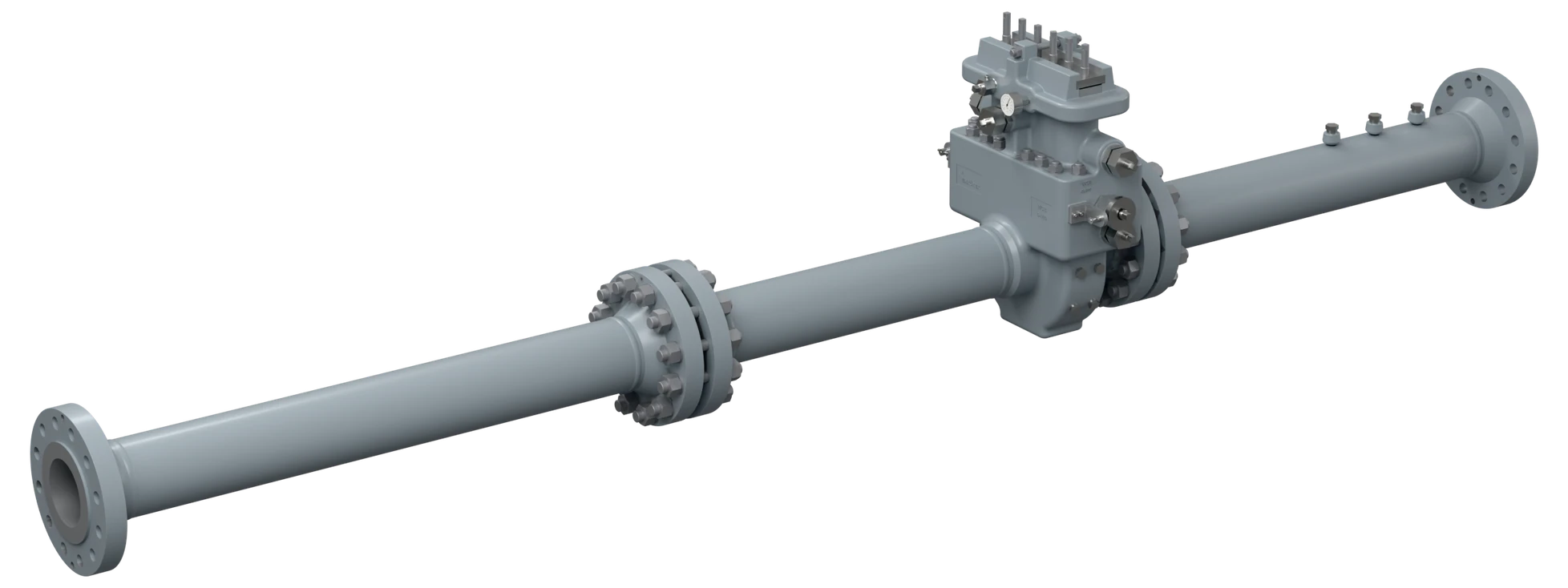
A perforated plate or tube bundle that removes swirl and rebuilds a fully developed velocity profile, so the primary element downstream sees the flow the standard assumes. The reason to fit one is almost always space: it buys back straight pipe you do not have.
Four conditioners
They differ in hole pattern, plate thickness and the permanent pressure loss they impose. Which one is qualified for a given installation depends on the run it is going into and the standard the project follows.
All four are patterns named in ISO 5167-1 Annex C and AGA Report No. 3 (API MPMS 14.3) Part 2, so a project can call them out by reference instead of by drawing. A conditioner earns that status by test rather than by geometry: it is installed behind a swirl generator and behind an asymmetric profile disturbance, and it passes only when the shift in the primary element's discharge coefficient stays inside the limit the standard sets against a fully developed baseline. İnkotek manufactures and verifies every flow conditioner against the qualified pattern, with hole layout, plate thickness and installed position held to the tolerances that the published performance depends on.
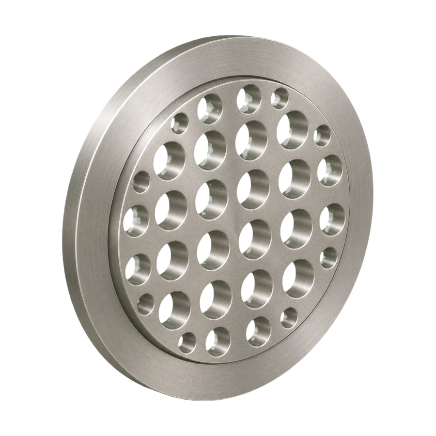
Zanker Conditioner
Perforated plate
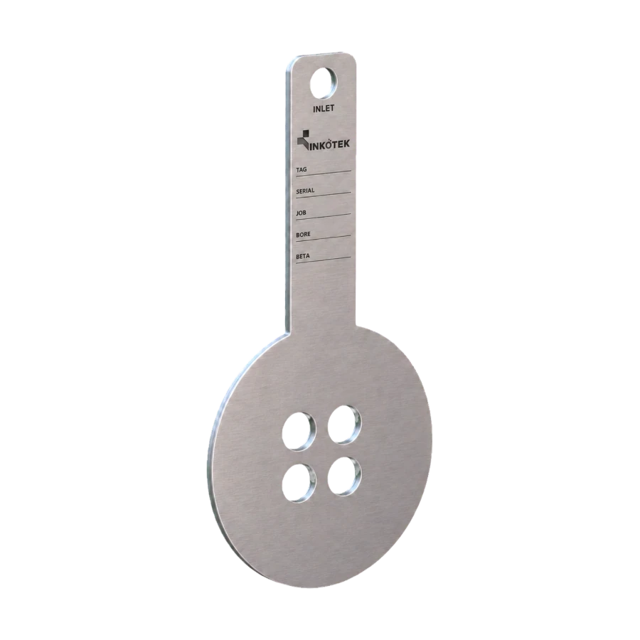
The classic perforated plate pattern: a single plate with a fixed hole pattern and no vanes behind it. Named in ISO 5167-1 Annex C and AGA-3 Part 2, with well documented performance and wide acceptance on gas metering runs.
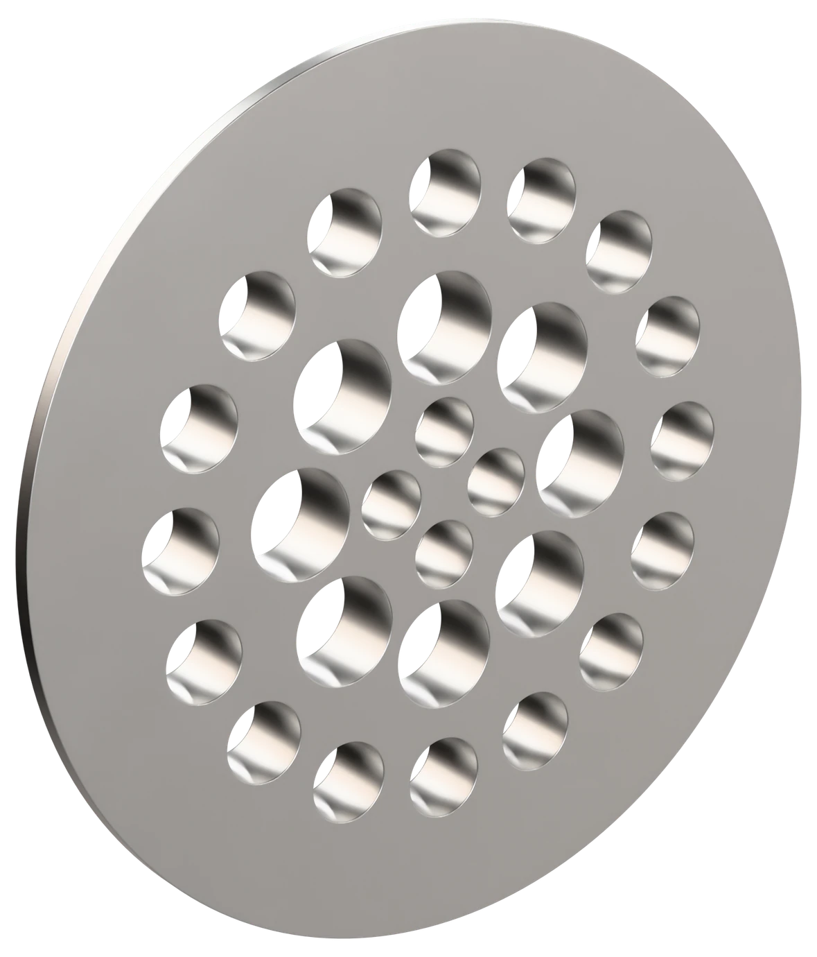
NEL (Spearman)
Perforated plate
Developed at the National Engineering Laboratory and carried in ISO 5167-1 Annex C. A single perforated plate with a graded hole pattern, effective against both swirl and profile distortion.
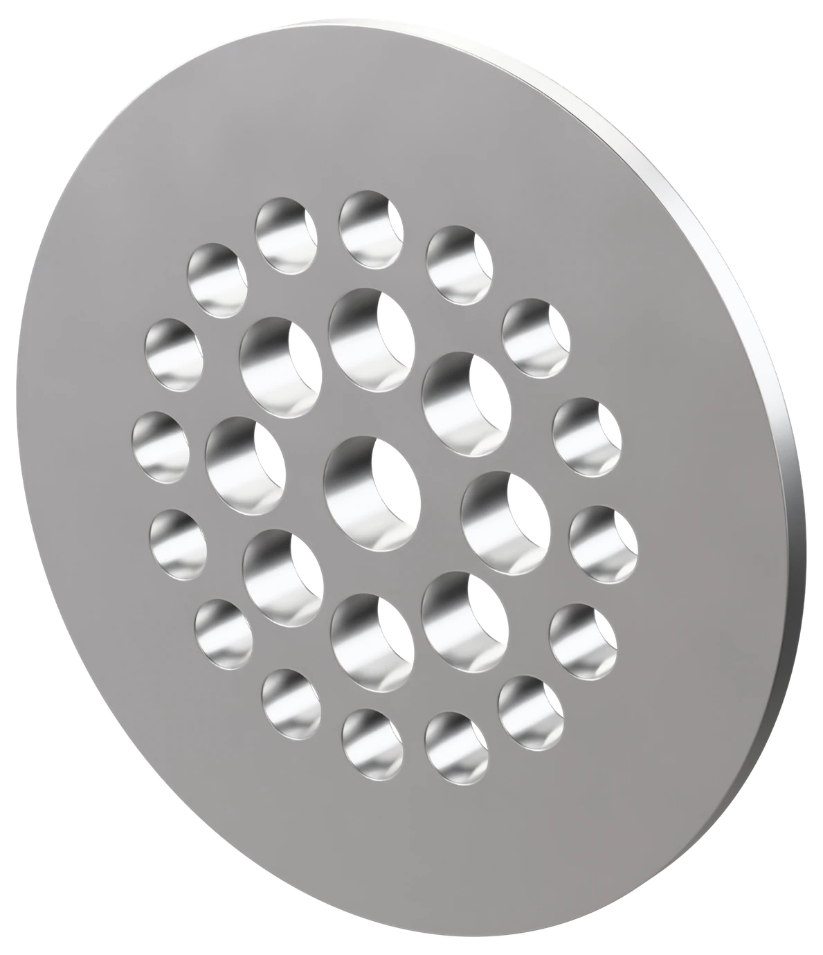
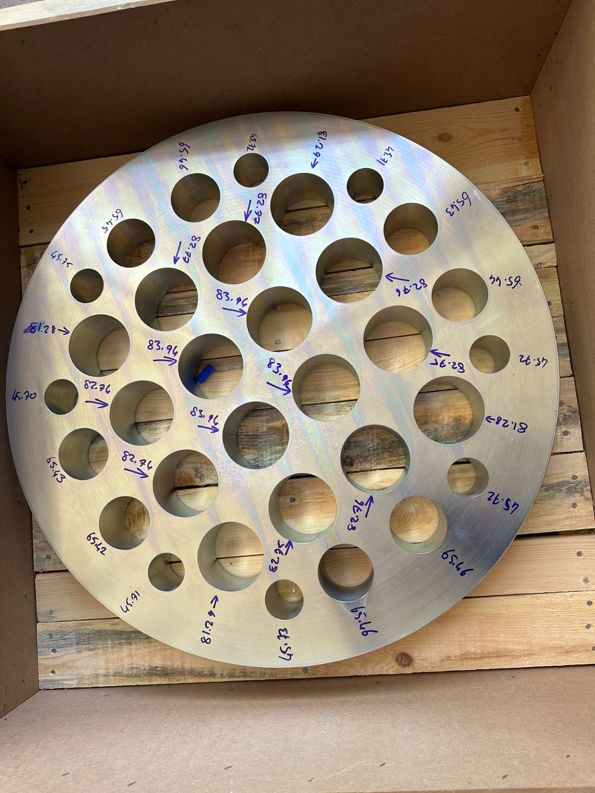
Laws Perforated Plate
Perforated plate
Thicker plate with a graded hole pattern optimised for short installed length — the Laws 1-8-16 plate, with the hole arrangement developed by Laws. Made to the K-Lab NOVA geometry given in ISO 5167-2, Annex B. The design is based on AGA-3 Part 2 performance test data. Used where the upstream run has to be compressed as far as it will go.
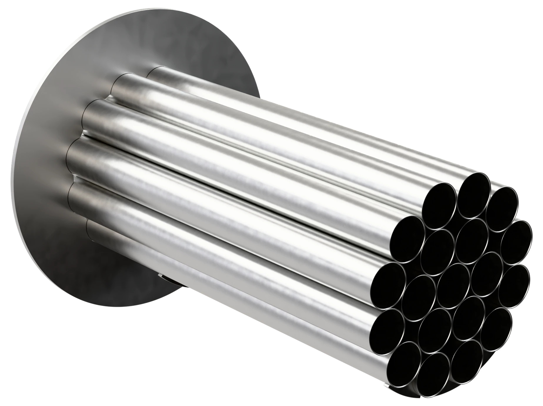
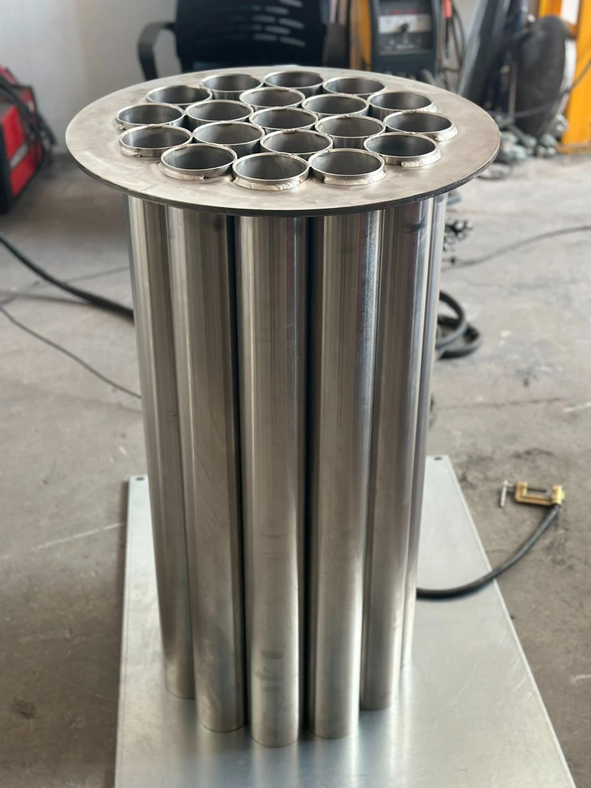
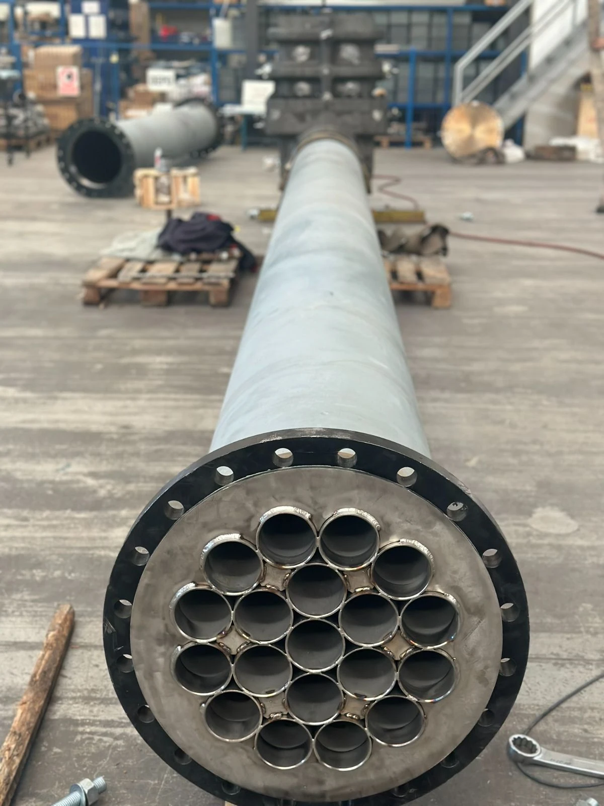
19-Tube Bundle Flow Straightener
Bundle of parallel tubes
A bundle of parallel tubes filling the bore, the arrangement AGA-3 Part 2 describes for swirl removal. Effective against swirl, but ISO 5167-1 treats it as a straightener only — it does less to correct an asymmetric profile than a perforated plate.
Technical data
| Size range | NPS 2″ – 44″ (DN 50 – DN 1100) |
| Pressure class | ASME Class 150 – 2500 |
| Types | Zanker, NEL (Spearman), Laws 1-8-16 plate, tube bundle |
| Mounting | Wafer between flanges or inserted into the fitting |
| Position | At the qualified distance upstream of the element, recorded on the drawing |
| Pressure loss | Typically 0.5 – 2 velocity heads depending on type |
| Marking | Tag number, line size, rating, type and flow direction on the plate edge or the tab |
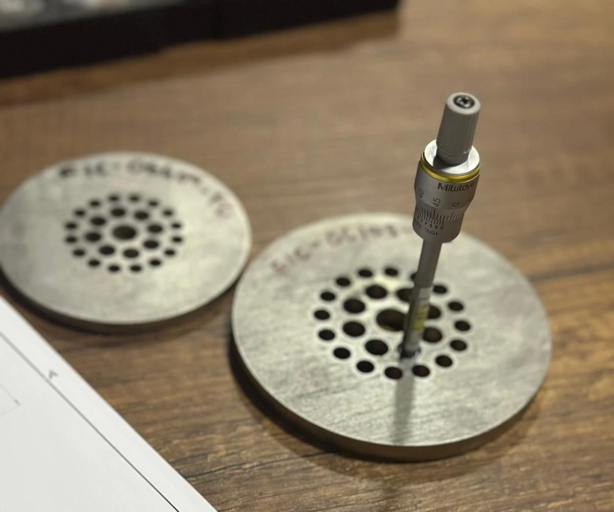
| Quality control | ISO 9001 system; hole pattern and plate thickness measured and recorded; EN 10204 3.1 certificates, 3.2 on request |
| Documentation | Dimensional report, material certificate (EN 10204 3.1) |
Zanker, NEL (Spearman) and Laws identify flow conditioner geometries published in the open literature and in the governing standards. Where a geometry is also known by a third party's product or company name, that name belongs to its owner; İnkotek Enerji is not affiliated with, endorsed by or licensed by those owners and manufactures no licensed or patent-protected product of theirs. Conditioners are manufactured to published geometry on which patent protection has expired, and are supplied with a dimensional report against that geometry. Where a published approval-of-type test report is referred to, it belongs to the party that commissioned it.
Material selection
The plate is a wetted element in the middle of the run, so it is selected for the medium and the service and mounted in a carrier that matches the line.
Where it runs
Sectors this family is specified into most often.
Dimension drawings
The hole pattern and plate thickness are fixed by the conditioner type and the line size, so each pattern is a drawing of its own — hole count, hole diameters, pitch circles and plate thickness against DN.
The distance from the conditioner to the primary element is given on the project drawing of the meter run, not on these pattern drawings. The position is what the qualification depends on; moving it invalidates the shortened straight run.
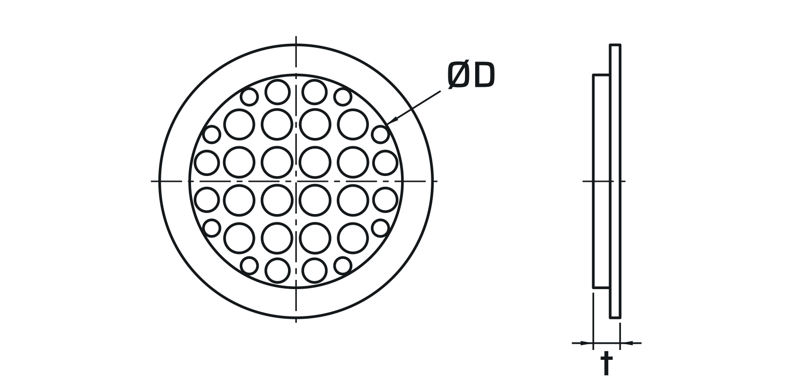
Zanker plate
Fixed hole pattern on five pitch circles, plate thickness by DN. The reference pattern for shortened runs.
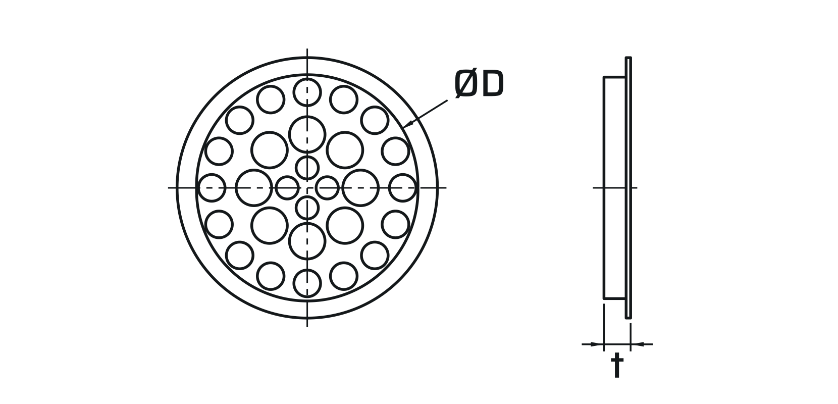
NEL (Spearman)
Different hole count and distribution, thinner section. Chosen where the permanent loss of the conditioner has to stay lower.
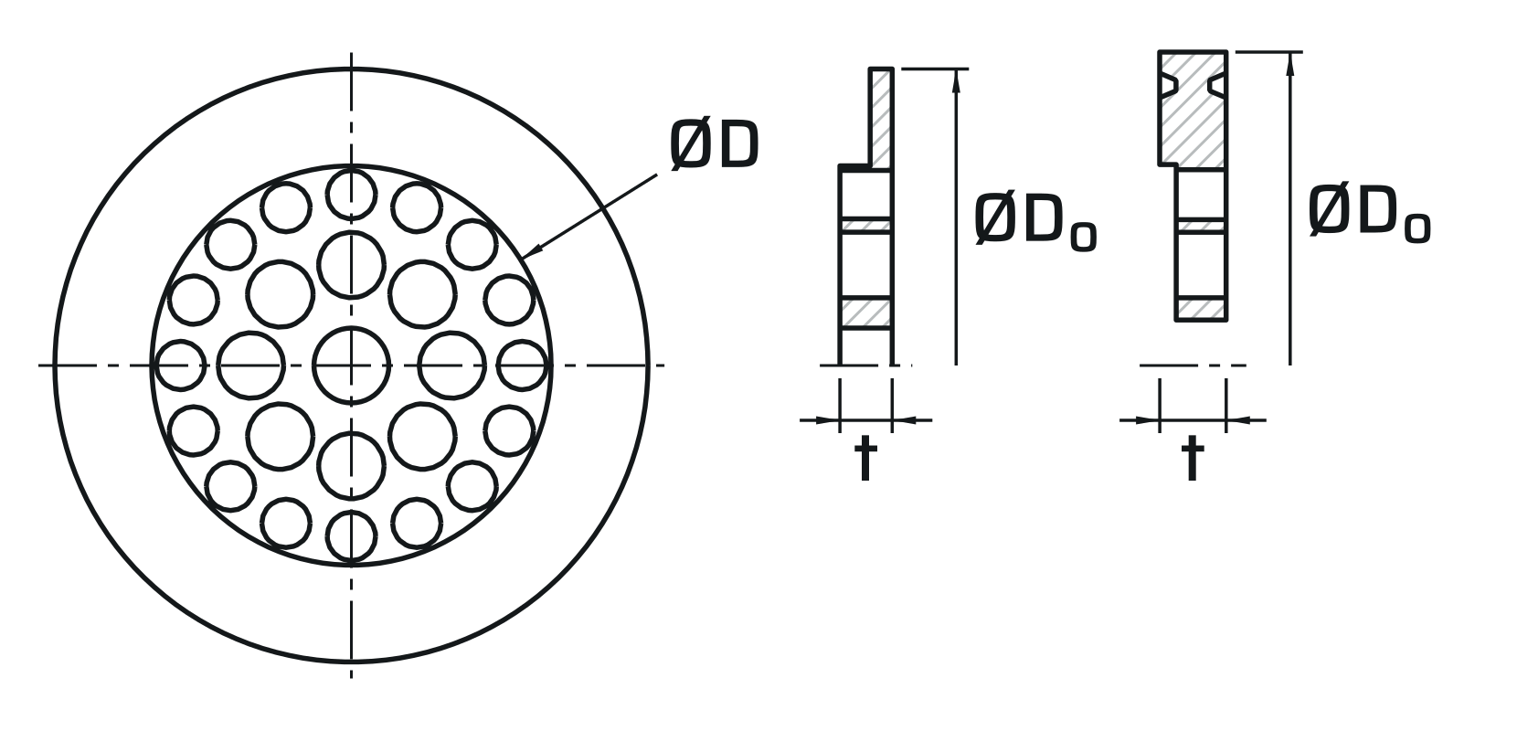
Laws plate
Supplied for raised face and RTJ joints; the outside diameter and the seating detail change with the facing.
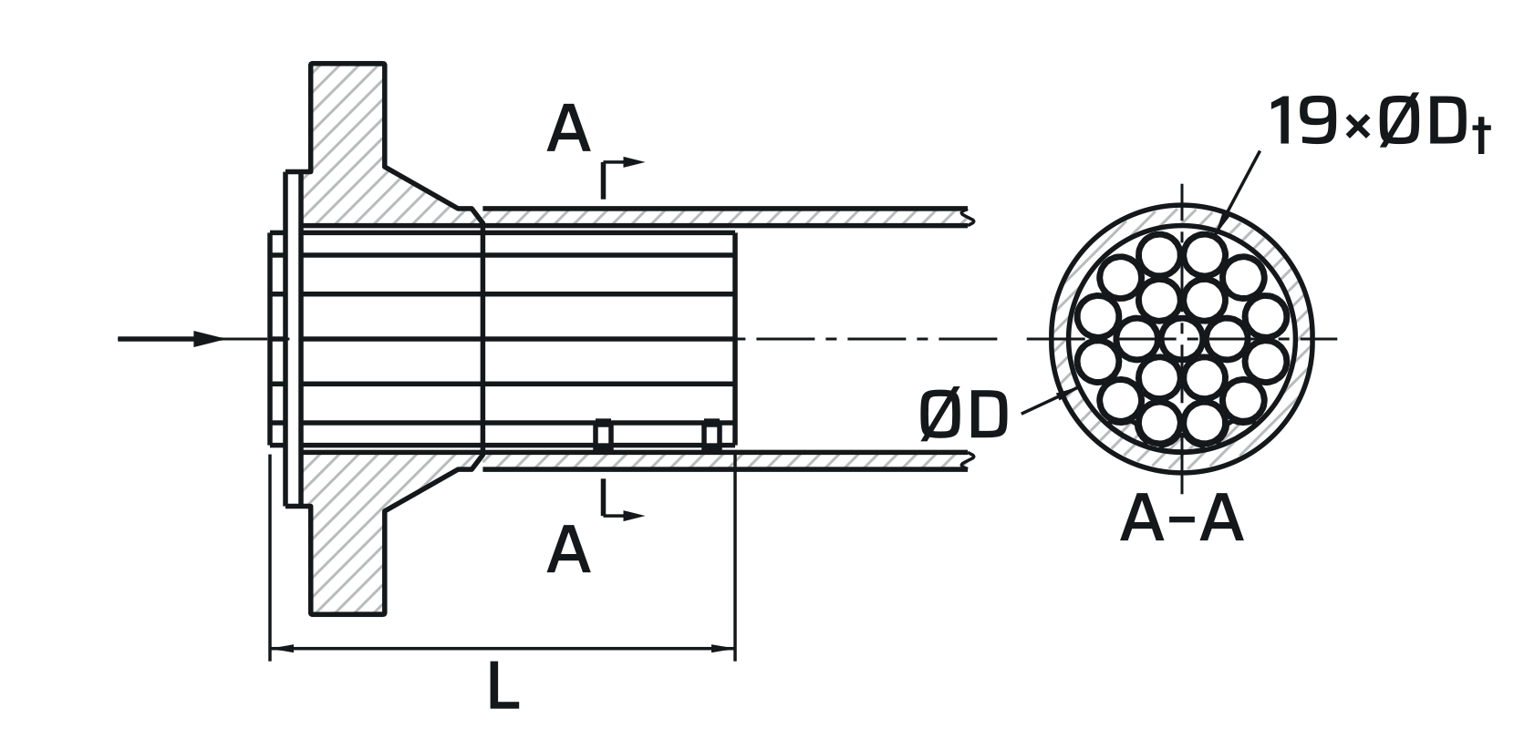
Tube bundle
Tube count, tube diameter and bundle length instead of a hole pattern. Longer envelope, fitted inside the spool.
Documents
- Flow conditioner: [Zanker / NEL (Spearman) / Laws 1-8-16 / tube bundle], line size [NPS …], rating [ASME Class …].
- Mounting: [wafer between flanges / inserted into the fitting], at the qualified distance upstream of the primary element, given on the meter run drawing.
- Geometry: hole pattern and plate thickness to the published geometry of the type, measured and recorded on a dimensional report.
- Materials: [ … ], to suit the process and the line piping class.
- Marking: tag number, line size, rating, type and flow direction on the plate edge or the tab.
- Documents: dimensional report, material certificate EN 10204 3.1 (3.2 where stated).
Flow Conditioners
Send the line size, the element downstream and the straight length you actually have between the last fitting and the plate. That decides which conditioner is qualified.