
Level Gauges and Level Tubes
Direct level reading at the vessel, and the standpipe that carries it. The gauge shows the operator where the level is without power or signal; the level tube gives the gauge, the switches and the transmitter one pair of connections to share instead of a penetration each.
Four arrangements
The medium decides the gauge. A clear liquid reads well on a reflex prism; anything coloured, viscous or layered needs light passing through the chamber instead.
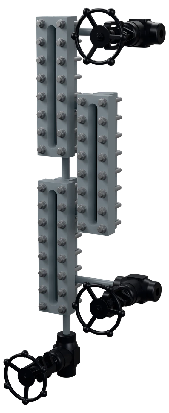
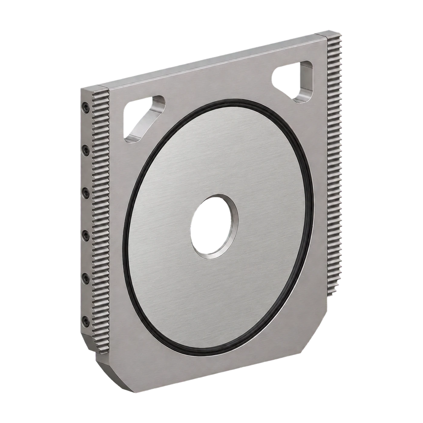
Reflex Level Gauge
Prismatic glass · DIN 7081
Grooved prism glass on a single face. Light entering the vapour space is reflected back and reads silver; where liquid wets the prism the light passes into it and the same face reads black, so the level is a sharp line between the two.
For clear liquids. Sections stacked and offset to cover a long span without a single oversized glass.
Transparent Level Gauge
Two glasses · interface service
Glass on both faces with the liquid between them, read against daylight or an illuminator behind. Mica shields sit between the glass and the medium on steam and alkaline duty, where the glass surface would otherwise be attacked.
For coloured, viscous or dirty liquids and liquid-liquid interfaces.
Tubular Level Gauge
Low pressure · direct glass tube
A borosilicate tube clamped between two valve bodies with a rod guard around it. The simplest arrangement, and the one to specify for atmospheric and low pressure tanks on non-hazardous service.
Up to about 7 bar; guard and drain cock included.
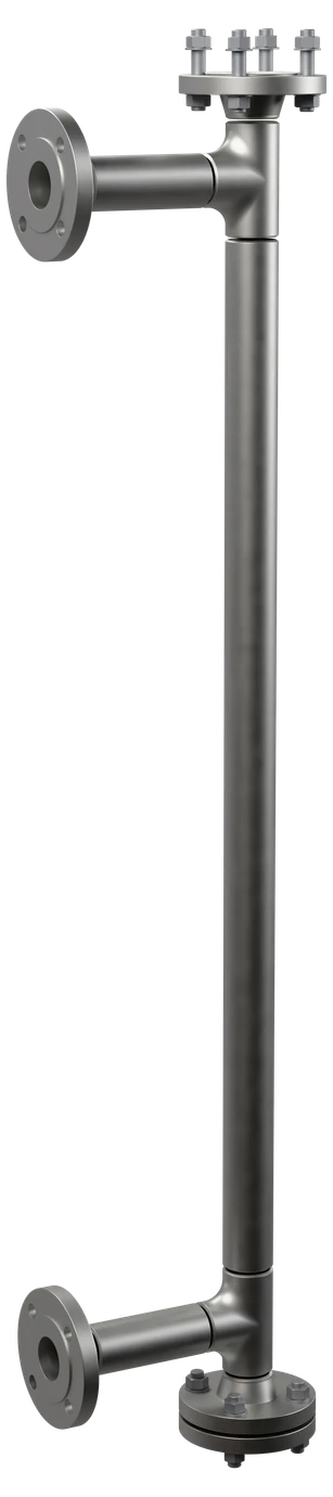
Level Tube (Standpipe)
Instrument carrier · isolation
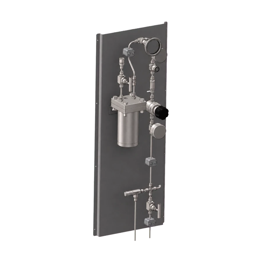
A seamless pipe standpipe with process connections top and bottom, isolation and drain valves, and the mounting points for the gauge, the level switches or a transmitter. One pair of vessel penetrations serves every instrument on the bridle.
Flanged, socket weld or threaded, drawn to your connection centres.
Technical data
| Gauge types | Reflex, transparent and tubular, single or multi-section |
| Visible length | 130 – 340 mm per section; sections combined to cover the measured span |
| Centre distance | Set by the vessel connections and confirmed on the arrangement drawing |
| Pressure rating | PN 16 – PN 400 / ASME Class 150 – 2500; reflex to 100 bar, transparent with mica to 250 bar |
| Temperature | Up to 300 °C reflex; up to 400 °C transparent with mica shields |
| Glass | Tempered borosilicate to DIN 7081, certificate supplied with the assembly |
| Sealing | PTFE, graphite or non-asbestos gaskets; mica shields on steam and alkaline duty |
| Gauge valves | Forged cocks with ball check, closing automatically if the glass fails; vent and drain included |
| Standpipe | Seamless pipe to ASME B36.10 / B36.19, sized so the level responds without lag |
| Instrument connections | Gauge glass, level switch, transmitter or magnetic indicator on the same standpipe |
| Design codes | DIN 7081 for the glass; EN 12952-11 / EN 12953-9 on boiler duty; ASME B31.1 / B31.3; PED 2014/68/EU |
| Marking | Tag number, rating, glass reference, material and heat number |
| Documentation | Hydrostatic test report, glass certificate, material certificate (EN 10204 3.1) |
Material selection
The chamber and the standpipe follow the vessel class. The glass and the shielding are chosen for the temperature and the chemistry, not the pressure alone.
Where it runs
Sectors this family is specified into most often.
What to send for sizing
The measured span and the vessel connection centres set the number of sections and the standpipe length. Both are drawn before fabrication and issued for approval.
Tell us what else goes on the standpipe. Switches, a transmitter or a magnetic indicator are cheaper to allow for now than to add later.
Sizing enquiry sheet →| What you send | What it decides |
|---|---|
| Gauge type required | Reflex, transparent, tubular, or a standpipe on its own |
| Measured span | The visible length and how many sections it takes to cover it |
| Vessel connection centres | Standpipe length and the position of the process connections |
| Design pressure and temperature | Glass type, mica shielding and the rating of the chamber |
| Medium | Whether a reflex prism can read it, or the duty needs light through the chamber |
| Connection type and facing | Flanged, socket weld or threaded, with the standard and rating |
| Other instruments on the standpipe | Level switches, transmitter or magnetic indicator, and their positions |
Documents
- Level gauge: [reflex / transparent / tubular], [single / multi]-section, visible length [ … mm] to cover the measured span, centre distance to the vessel connections [ … mm].
- Rating: [PN … / Class …]; reflex up to 100 bar and 300 °C, transparent with mica shields up to 250 bar and 400 °C.
- Glass: tempered borosilicate to DIN 7081, certificate supplied.
- Gauge valves: forged cocks with ball check, closing automatically if the glass fails; vent and drain.
- Sealing: [PTFE / graphite / non-asbestos] gaskets; mica shields on steam and alkaline duty.
- Codes: [EN 12952-11 / EN 12953-9] on boiler duty; [ASME B31.1 / ASME B31.3]; PED 2014/68/EU.
- Marking and documents: tag number, rating, glass reference, material and heat number; hydrostatic test report, glass certificate, material certificate EN 10204 3.1.
Level Gauges and Level Tubes
Send the gauge type, the measured span, the vessel connection centres and the design pressure and temperature. If switches or a transmitter will go on the standpipe, say so now.