
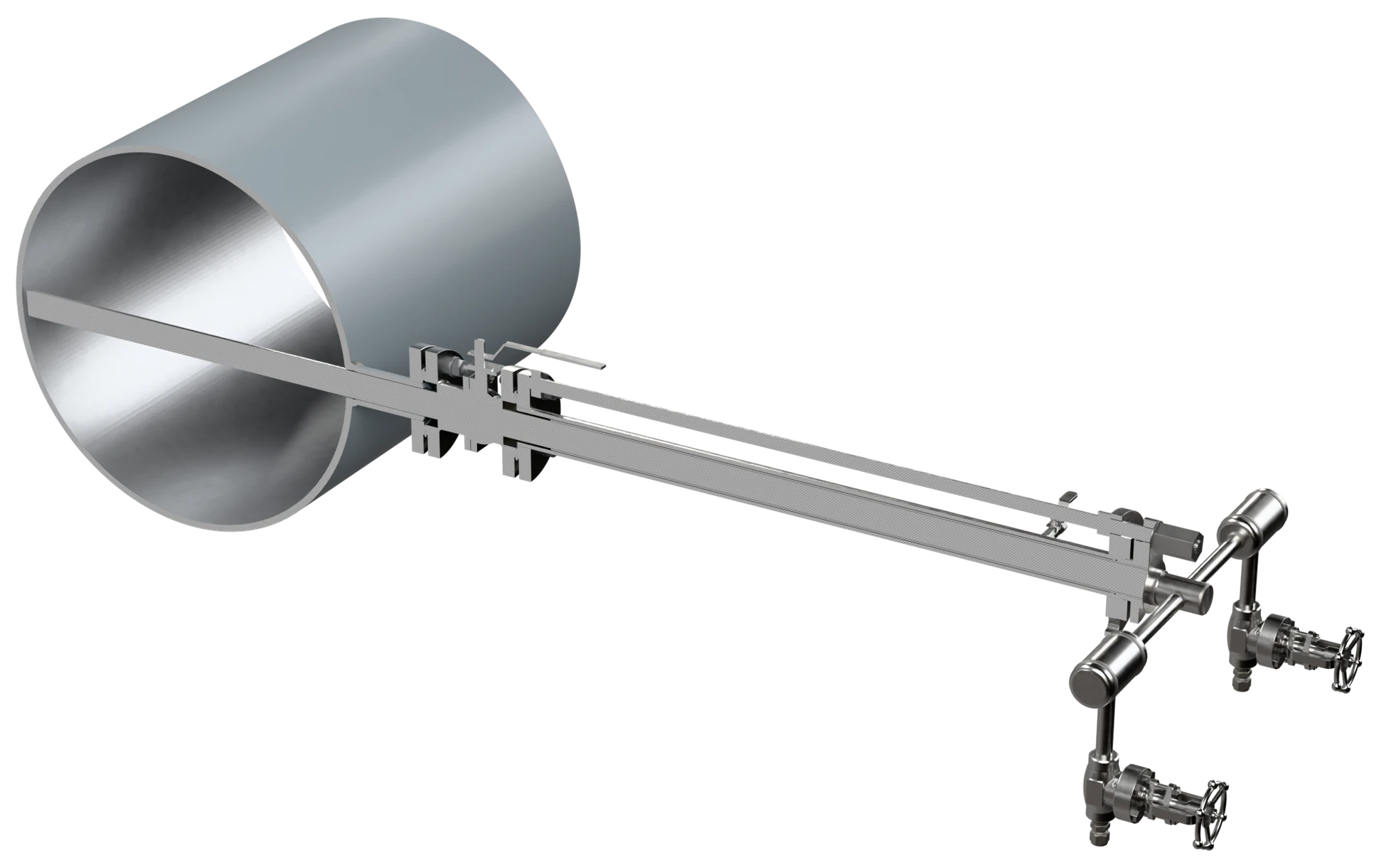
Pitot Tubes
An insertion element rather than an in-line one. The probe crosses the pipe and averages the velocity profile across the diameter, so it can be fitted to a large line or a rectangular duct through a single connection on one side — on larger lines the probe tip is held in a support on the opposite wall — with a low permanent pressure loss.
Three arrangements
The difference is the shape of the duct and whether the probe has to come out while the line is running.
Averaging Pitot Tube
Single probe · round pipe
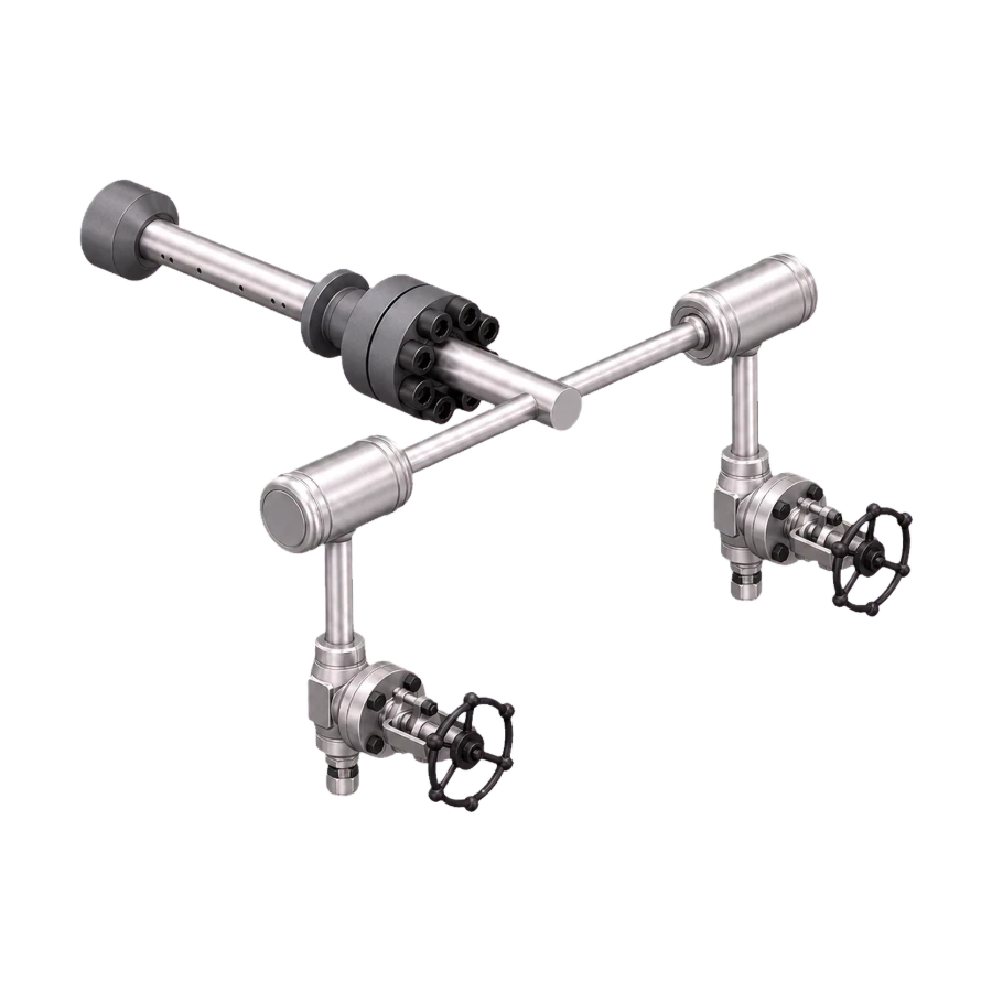
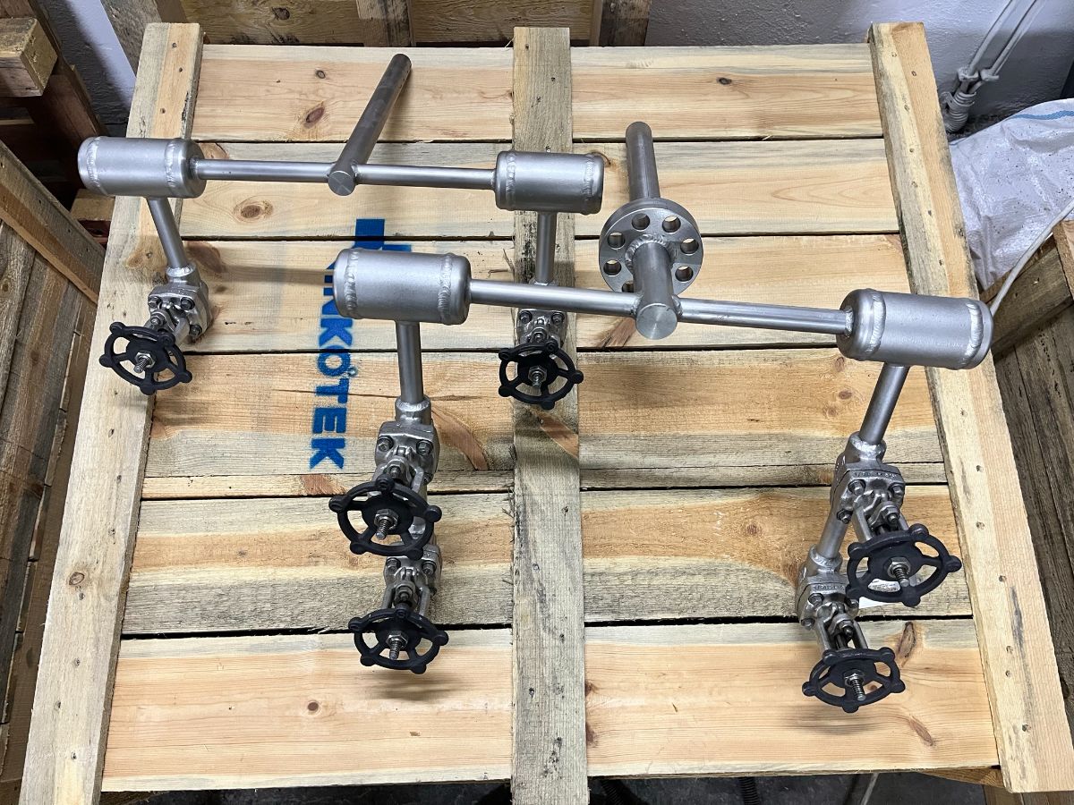
A sensing rod with impact ports along one face, mounted through a flanged or threaded connection on the side of the pipe; on steam and liquid lines the probe lies horizontal. Optional integral manifold and differential pressure transmitter.
Grid Type Pitot Tube
Large ducts, rectangular sections
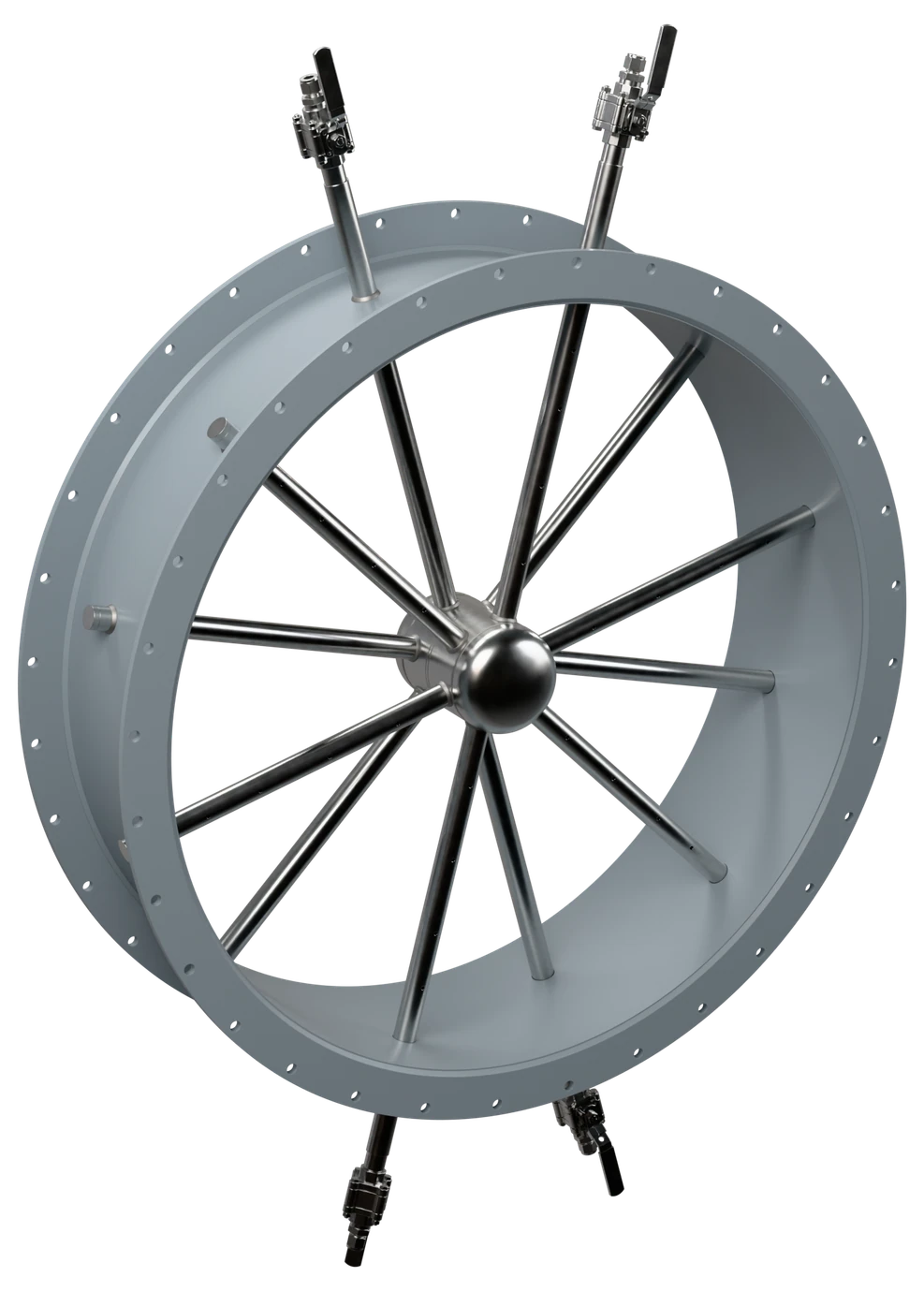
Several probes arranged on a grid across a large or rectangular duct, manifolded to a single pair of connections. Used on combustion air and flue gas ducts.
Retractable Assembly
Removable without shutdown
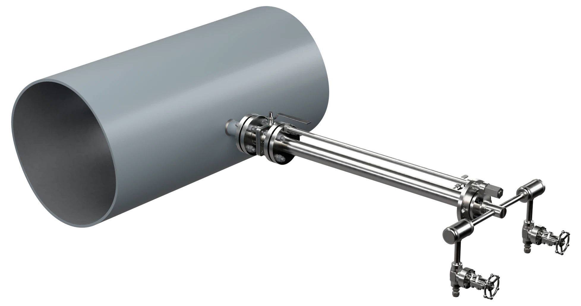
Packing gland and withdrawal mechanism allowing the probe to be pulled clear of the bore while the line stays in service.
Technical data
| Line size | NPS 4″ – 120″ (DN 100 – DN 3000); rectangular ducts on request |
| Pressure class | EN 1092-1 PN 16 – PN 160 / ASME Class 150 – 1500 (process connection) |
| Design basis | Outside ISO 5167; flow coefficient K on the calculation sheet |
| Probe construction | Solid or tubular sensing rod with machined impact ports |
| Process connection | Flanged, threaded, or welded boss with packing gland |
| Insertion | Fixed insertion, or retractable under pressure; withdrawal limits, blow-out protection and isolation valve to the approved design |
| Options | Integral three or five valve manifold, DP transmitter, temperature sensor |
| Measuring uncertainty | Stated on the calculation sheet for the duty |
| Permanent pressure loss | Low: the probe blocks only its own frontal area; the loss rises with the share of the bore it blocks and is stated on the calculation sheet |
| Marking | Tag number, line size, insertion length, material and flow direction, marked on the head |
| Quality control | ISO 9001 system; pressure-retaining parts to PED where it applies; EN 10204 3.1 certificates as standard, 3.2 on request |
| Documentation | Sizing calculation, material certificate (EN 10204 3.1) |
Material selection
The probe stands in the stream and carries the whole load, so it drives the selection; the mounting follows the line.
Where it runs
Sectors this family is specified into most often.
What to send for sizing
There is no dimension table for the family. Insertion length comes out of the pipe or duct dimension, the wall thickness and the height of the mounting boss, and the port positions follow the averaging arrangement for that size — every probe is drawn for its own line.
The retraction envelope is given on the approval drawing so the clearance beside the connection can be reserved before the boss is welded.
Sizing enquiry sheet →| Process data | What it decides |
|---|---|
| Pipe or duct dimension | Inside diameter, or the width and height of a rectangular duct |
| Wall thickness and insulation | Sets the boss height and the insertion length |
| Medium, phase and temperature | Decides probe material, port size and gland packing |
| Flow range — min, normal, max | Sets the probe size and the differential at each point |
| Operating pressure | Fixes the connection rating and the gland arrangement |
| Mounting position and clearance | Where on the circumference, and the free space above the connection |
| Straight length available | Upstream and downstream, measured from the nearest fitting |
| Removal under pressure needed? | Decides fixed insertion or a retractable assembly |
Documents
- Primary element: Pitot tube, [fixed insertion / retractable under pressure], for line size [NPS …] or rectangular duct [ … ].
- Design basis: outside ISO 5167; flow coefficient K stated on the calculation sheet.
- Probe: [solid / tubular] sensing rod with machined impact ports.
- Process connection: [flanged, rating PN … / Class … / threaded / welded boss with packing gland]; on retractable probes, withdrawal limits, blow-out protection and isolation valve.
- Options where specified: [integral three / five valve manifold, DP transmitter, temperature sensor].
- Marking on the head: tag number, line size, insertion length, material and flow direction.
- Documents: sizing calculation, material certificate EN 10204 3.1 (3.2 where stated); pressure-retaining parts to PED where it applies.
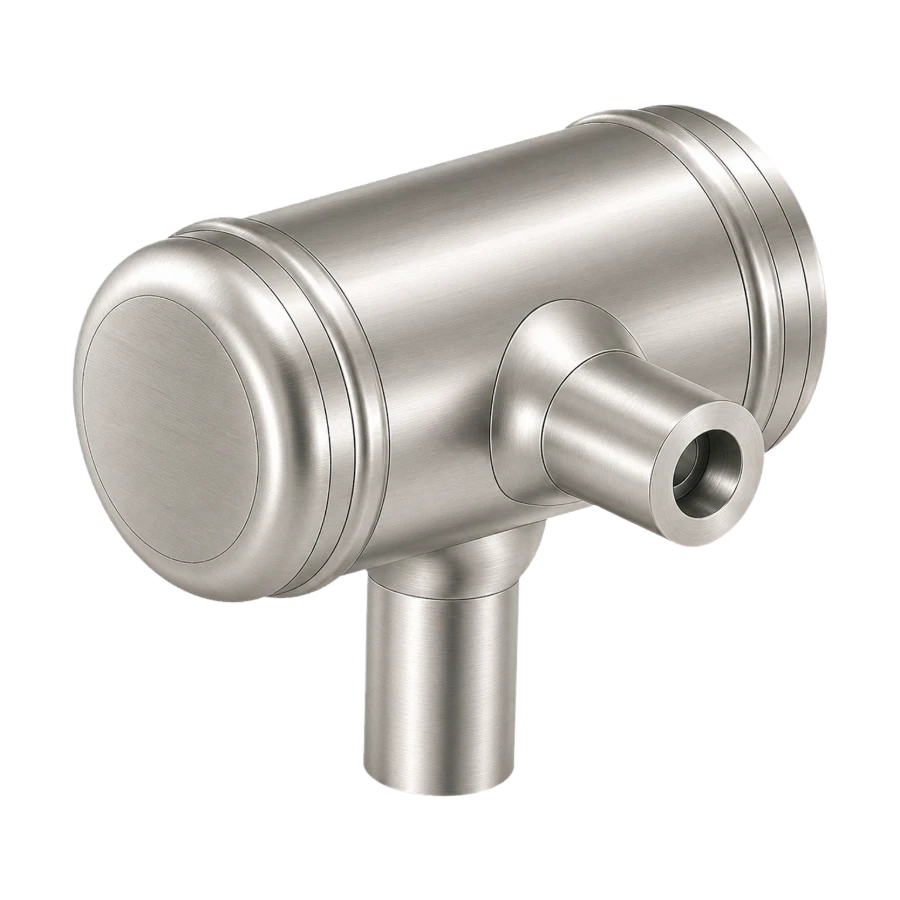
Pitot Tubes
Send the pipe or duct dimension, the flow range and the medium, and say whether the probe has to be removable while the line is running.