
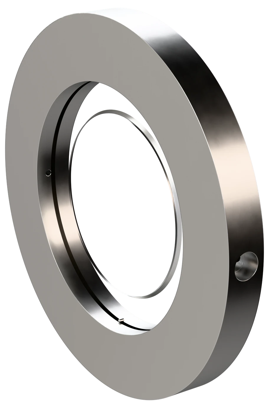
Compact Orifice Assembly
The plate and its pressure tappings in one body. Nothing has to be built around it on site — no orifice flange pair, no impulse piping and, where the transmitter mounts directly, no tubing at all. That makes it the practical element for small lines, where a conventional flange union would be larger and heavier than the pipe it measures.
Three builds, one principle
All three take the differential across the same machined plate. What changes is how the tappings are formed and how the transmitter reaches them.
Tapping Holes
Wafer body · corner tappings
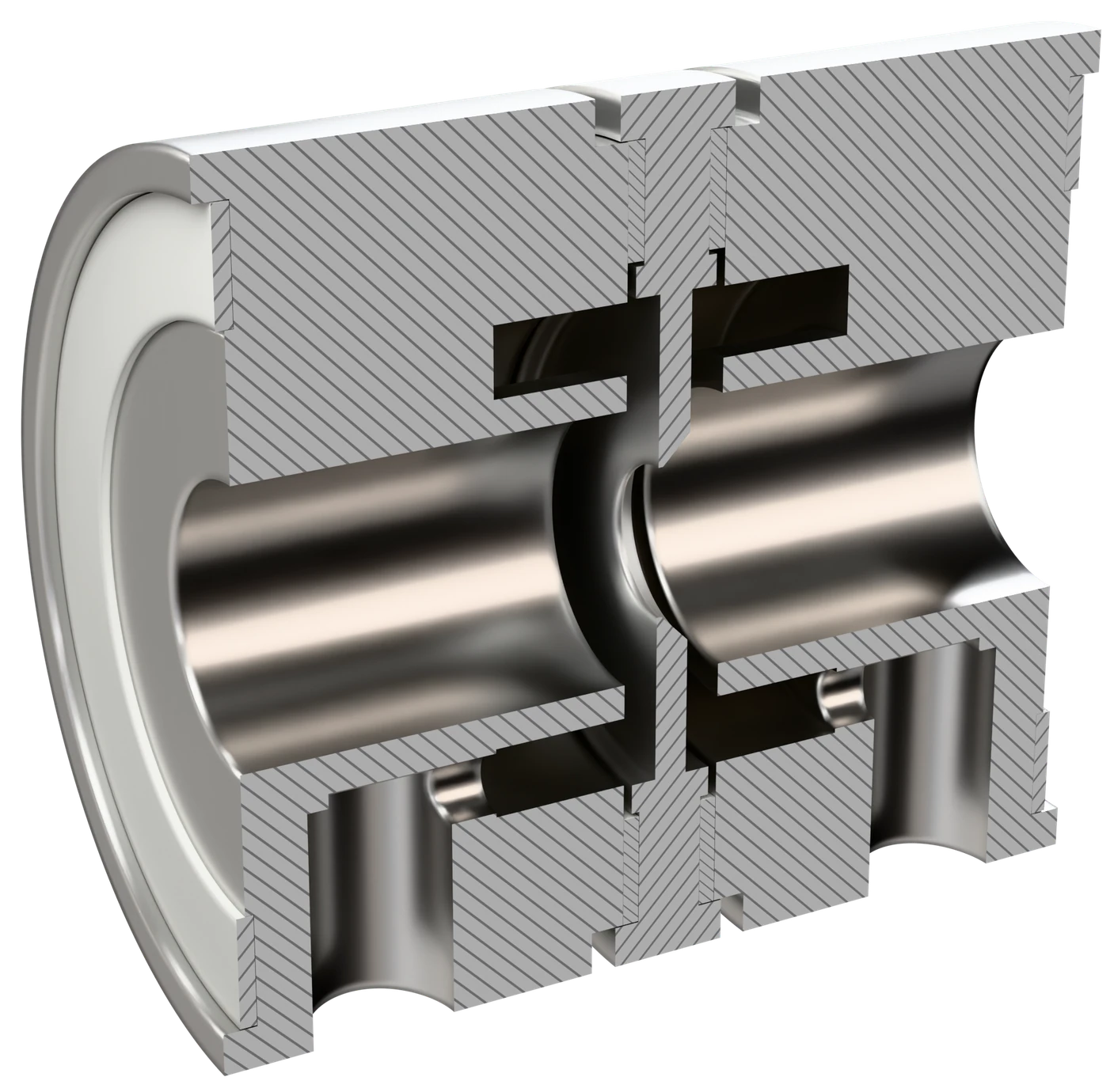
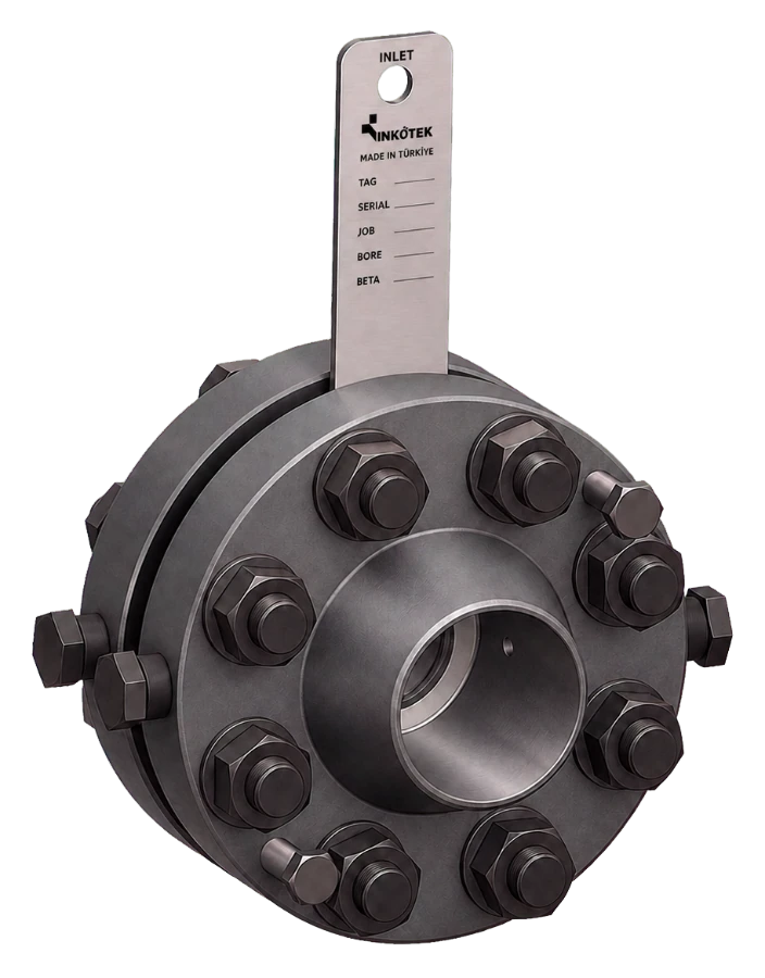
Two tappings drilled through the body, one either side of the plate, opening into the pipe at the corner position. The simplest build and the one used where the line is clean and single-phase.
Clamped between the line flanges; no orifice flanges required.
Annular Tapping Groove
Averaged corner tapping
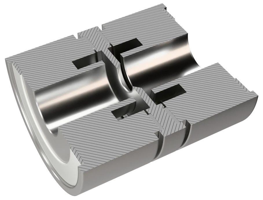
A groove machined into each face of the body averages the pressure around the full circumference, which removes the sensitivity to where a single tapping hole happens to sit.
Preferred where the velocity profile at the plate may be slightly uneven; the straight lengths the standard requires still apply.
Integral Meter Body
Direct mounted transmitter · IEC 61518
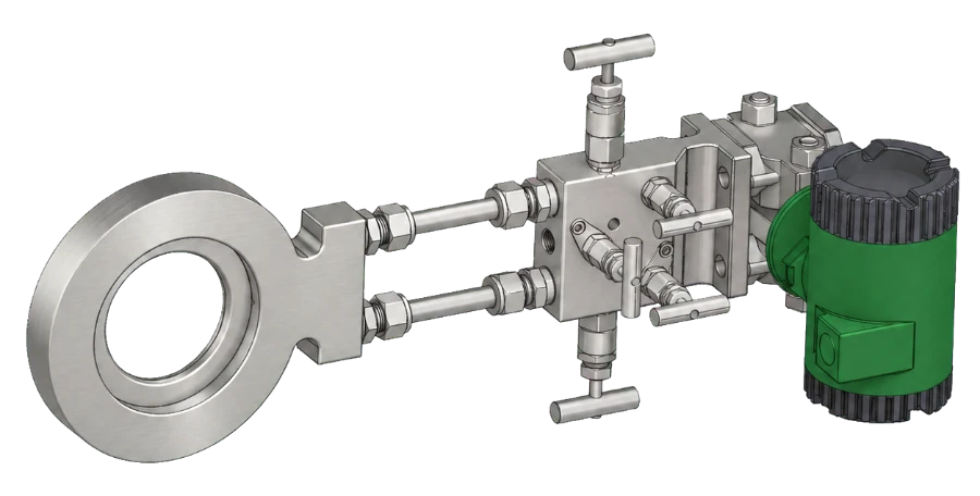
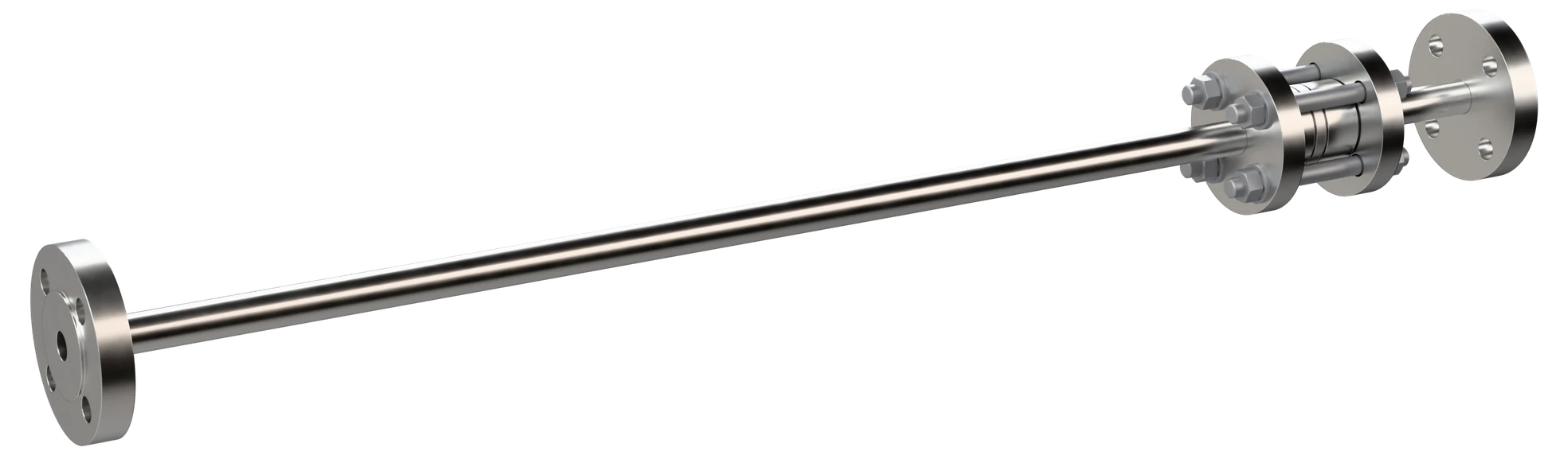
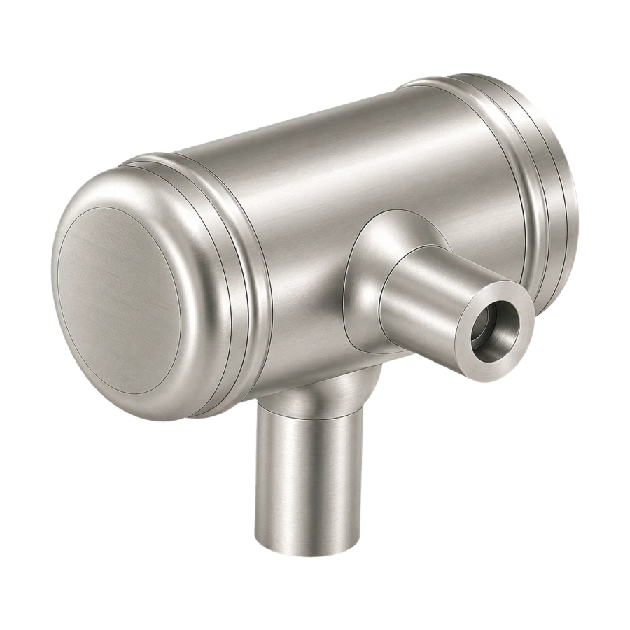
A meter body with its own machined bore and end connections, carrying the plate and the transmitter as one assembly. The transmitter bolts straight onto the tapping face, so there are no impulse lines to fill, freeze or leak.
Threaded, socket weld or flanged ends; manifold and valves included.
Technical data
| Bore type | Concentric; multi-hole (conditioning) or quadrant edge on request |
| Line size | DN 15 – DN 100 (½″ – 4″) |
| Pressure rating | To the line flanges: ASME B16.5 Class 150 – 2500, EN 1092-1 PN 6 – PN 400 or other standards |
| Design standard | ISO 5167-2 where D ≥ 50 mm; below that, ASME MFC-14M where the body sits in a conforming meter tube with annular-slot corner taps; otherwise ISO/TR 15377 or flow calibration |
| Pressure tappings | Through tapping holes in the body, or an annular groove machined into both faces |
| Tapping interface | ¼″ NPT, compact face per IEC 61518 for direct transmitter mounting, or compression fitting |
| Beta ratio | 0.10 – 0.75; low beta is normal in small lines and is set by the flow range |
| Measuring uncertainty | Stated on the calculation sheet for the duty; where built to ISO 5167-2, discharge coefficient uncertainty 0.50 % at β 0.50, 0.75 % at β 0.75; where the assembly is flow calibrated, the calibration sets it |
| Pressure loss | About 95 % of the differential at β 0.20, 73 % at β 0.50 and 45 % at β 0.75, falling as β rises (ISO 5167-2, 5.4.1) |
| Face to face | Fixed by the body design and issued on the installation drawing; no orifice flange pair is added to the line |
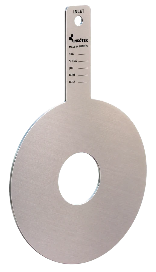
| Marking | Tag number, bore, beta, material, heat number and flow direction; marked on a welded paddle where one is fitted, otherwise on a stainless nameplate hung with stainless wire |
| Quality control | ISO 9001 system; bore diameter measured and recorded; hydrostatic test, or pneumatic where the project specifies, on welded builds; EN 10204 3.1 certificates, 3.2 on request |
| Documentation | Sizing calculation, dimensional report, material certificate; calibration certificate where the assembly is flow calibrated |
| Notes | Quality control — edge: visual check for d ≥ 25 mm; contour or optical measurement of the edge radius on request; below d = 25 mm, edge radius measurement or flow calibration, stated with the order (ISO 5167-2, 5.1.7.2). |
Material selection
The body and the plate are both wetted, so one grade usually covers the assembly. The gasket and the transmitter wetted parts are specified with it.
Where it runs
Sectors this element is specified into most often.
What to send for sizing
ISO 5167-2 does not cover pipe bores below 50 mm, and in small lines the Reynolds number at minimum flow often falls below the range of the standard in use. We check this against your flow data first, and say plainly whether the bore can be calculated or whether the assembly should be flow calibrated.
The bore d and the installation drawing are part of the scope of supply.
Sizing enquiry sheet →| Process data | What it decides |
|---|---|
| Build required | Tapping holes, annular groove or integral meter body |
| Line size and schedule | Sets the internal diameter D used in the calculation |
| Flange standard, rating and facing | Sets the body outside diameter and the bolt circle it has to fit |
| Medium, phase and density | Steam, gas and liquid are sized differently |
| Flow range — min, normal, max | Sets beta, the differential and whether calibration is needed |
| Pressure and temperature | Operating and design, both |
| Transmitter interface | Direct mount per IEC 61518, manifold mounted, or remote impulse lines |
Documents
- Primary element: compact orifice assembly fitted between the line flanges, with no orifice flange pair added; line size [DN 15 – DN 100], rating to the line flanges [Class … / PN …]; face to face as given on the installation drawing.
- Design: ISO 5167-2 where D ≥ 50 mm; below that, ASME MFC-14M in a conforming meter tube with annular-slot corner taps, otherwise ISO/TR 15377 or flow calibration.
- Bore: [concentric] ([quadrant edge / multi-hole (conditioning)] where specified); β 0.10 – 0.75, set by the flow range.
- Tappings: [tapping holes through the body / annular groove in both faces]; interface [¼″ NPT / IEC 61518 face for direct transmitter mounting / compression fitting].
- Materials: [ … ], to suit the process and the line piping class.
- Marking: tag number, bore, β, material, heat number and flow direction, on a welded paddle or a stainless nameplate.
- Inspection and documents: bore measured and recorded; hydrostatic test on welded builds; sizing calculation, dimensional report, material certificate EN 10204 3.1 (3.2 where stated); calibration certificate where the assembly is flow calibrated.
Compact Orifice Assembly
Send the build you need — tapping holes, annular groove or integral meter body — with the line size, the flange rating and the process data.