
Wedge Meter
The element for a medium that will not leave a sharp edge sharp. Slurries, heavy oil and anything abrasive or viscous, measured by a wedge welded into the pipe body rather than a plate held between flanges.
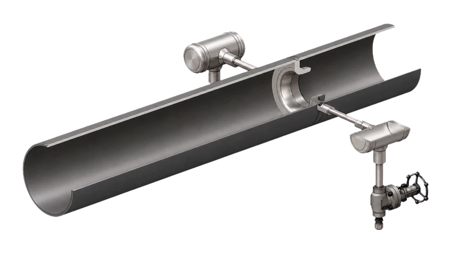
A wedge in the body, not a plate between flanges
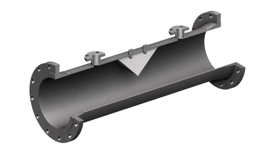
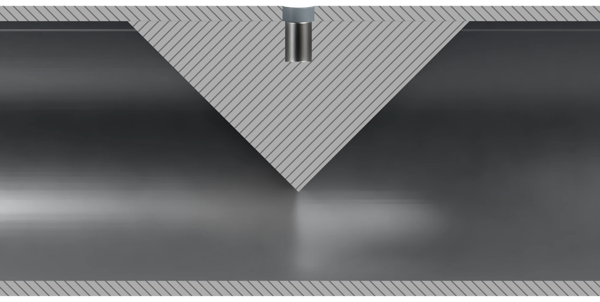
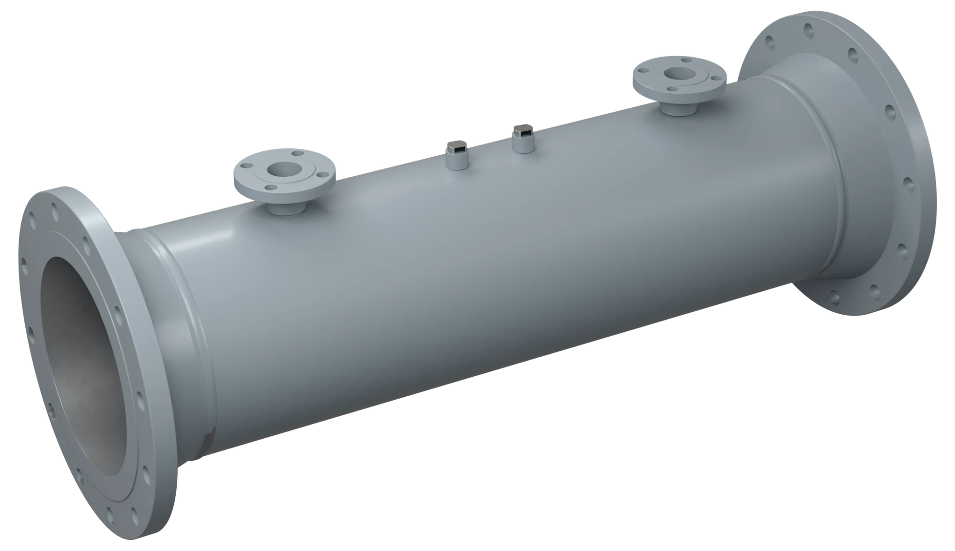
A 90° wedge is welded across the top of the bore, leaving a gap h below its apex, with the pressure tappings on the wedge side, either side of it. There is no plate between flanges and no part suspended in the stream.
Solids and heavy liquid pass under the wedge instead of collecting against a plate face. The apex still decides the coefficient: where the medium would round it off, the wedge is hardfaced.
Advantages
Technical data
| Size range | NPS 1″ – 48″ (DN 25 – DN 1200) |
| Pressure class | EN 1092-1 PN 6 – PN 400 / ASME Class 150 – 2500, other flange standards to the project; butt weld ends: by pressure design |
| Standards | ISO 5167-6 |
| Wedge ratio | h/D 0.2 – 0.5 (h: wedge gap, apex to opposite wall) |
| Uncalibrated limits | D 50 – 600 mm, h/D 0.2 – 0.6, Reynolds number 1 × 10⁴ – 9 × 10⁶ (ISO 5167-6) |
| Calibrated range | Outside those limits, the full size range with flow calibration, on request at an accredited laboratory |
| Upstream straight run | 7D – 22D by the upstream fitting; 15D clear of a partially closed valve (ISO 5167-6) |
| Tappings | Pipe wall either side of the wedge |
| End connections | Flanged, butt weld, wafer |
| Measuring uncertainty | Stated on the calculation sheet for the duty; discharge coefficient uncertainty 4 % uncalibrated (ISO 5167-6); flow calibration on request, at an accredited laboratory |
| Permanent pressure loss | About 79 % of the differential at h/D 0.2, 61 % at 0.4, 53 % at 0.5 (ISO 5167-6) |
| Marking | Tag number, size, rating, h/D ratio, material and flow direction; marking method to the project |
| Quality control | ISO 9001 system; PED where it applies; qualified welding procedures and NDE; EN 10204 3.1 certificates, 3.2 on request |
| Documentation | Sizing calculation, dimensional report, material certificate (EN 10204 3.1) |
Material selection
The wedge takes the wear and the body follows the line pipe. Both are specified before the tapping arrangement.
Where it runs
Sectors this family is specified into most often.
What to send for sizing
The wedge gap h and the h/D ratio come out of the sizing calculation. ISO 5167-6 fixes the geometry, the tapping positions and the calibration method; the finished dimensions are issued on the approval drawing once the calculation is agreed.
Send the following with the enquiry. What is in the fluid matters more here than the line size — it sets both the wedge ratio and the hardfacing.
Sizing enquiry sheet →| Process data | What it decides |
|---|---|
| Line size and schedule | Sets the bore and the wedge gap h |
| Flange standard, rating and facing | Or a butt weld / wafer preference |
| Medium, solids content and particle size | Decides the wedge ratio and whether hardfacing is needed |
| Viscosity at operating temperature | Sets the Reynolds number; below 10 000 the wedge is flow calibrated |
| Flow range — min, normal, max | Sets h/D and the differential at each point |
| Pressure and temperature | Operating and design, both |
| Tapping arrangement | Remote seals or chambers where the medium must not stand in a leg |
Documents
- Primary element: wedge meter, line size [NPS …], rating [Class … / PN …], [flanged / butt weld / wafer] ends, wedge ratio h/D [0.2 – 0.5] to suit the duty.
- Design: ISO 5167-6; uncalibrated within D 50 – 600 mm, h/D 0.2 – 0.6 and Reynolds number 1 × 10⁴ – 9 × 10⁶; outside these limits, flow calibration at an accredited laboratory.
- Tappings: pipe wall either side of the wedge.
- Installation: upstream straight length to ISO 5167-6 for the upstream fitting [ … D].
- Materials: [ … ], to suit the process and the line piping class.
- Marking: tag number, size, rating, h/D ratio, material and flow direction.
- Fabrication and documents: qualified welding procedures and NDE; sizing calculation, dimensional report, material certificate EN 10204 3.1 (3.2 where stated); calibration certificate where flow calibrated.
Wedge Meter
Send the medium, the solids content or viscosity, and the flow range. What is in the fluid decides the wedge ratio and the material.