
Flow Nozzles
A shaped convergent inlet instead of a square edge. The nozzle reaches the same differential pressure through a larger bore than a plate would need, which makes it the element of choice at high velocity, high temperature and where an eroding square edge would not survive the service life.
Four profiles, chosen by standard and by service
The profiles are not interchangeable — each carries its own discharge coefficient and its own tapping geometry. The choice usually follows the standard the project is specified to.
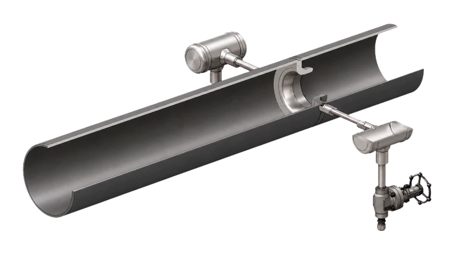
ISA-1932 Nozzle
ISO 5167-3
The European reference profile: a flat inlet and a two-arc convergent into a short cylindrical throat, with corner tappings. Well characterised coefficient, tight geometric tolerances.
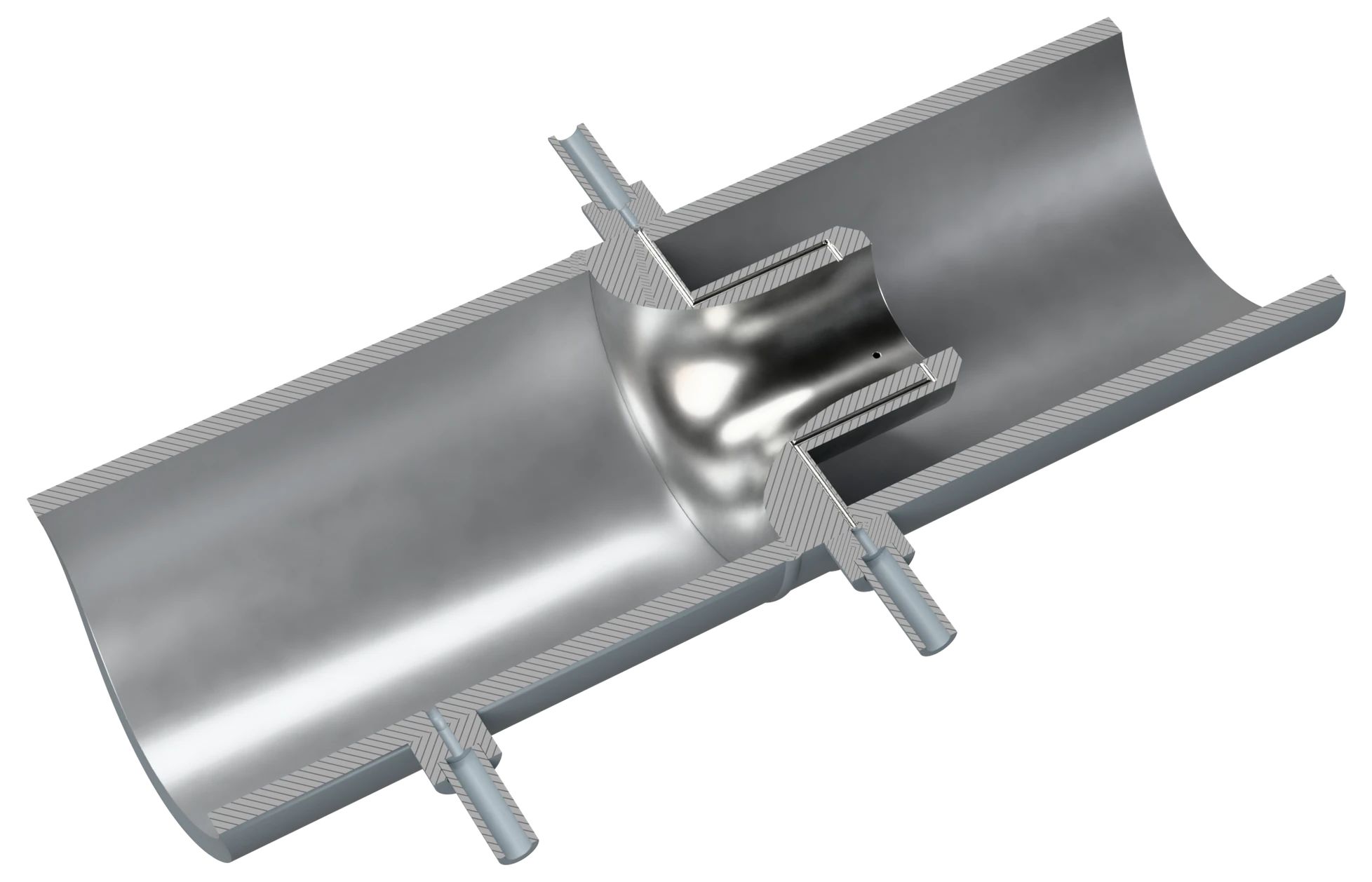
Long Radius Nozzle
ISO 5167-3 · ASME MFC-3M
An elliptical convergent section over a longer length, in high and low ratio forms. Common on North American power plant specifications.
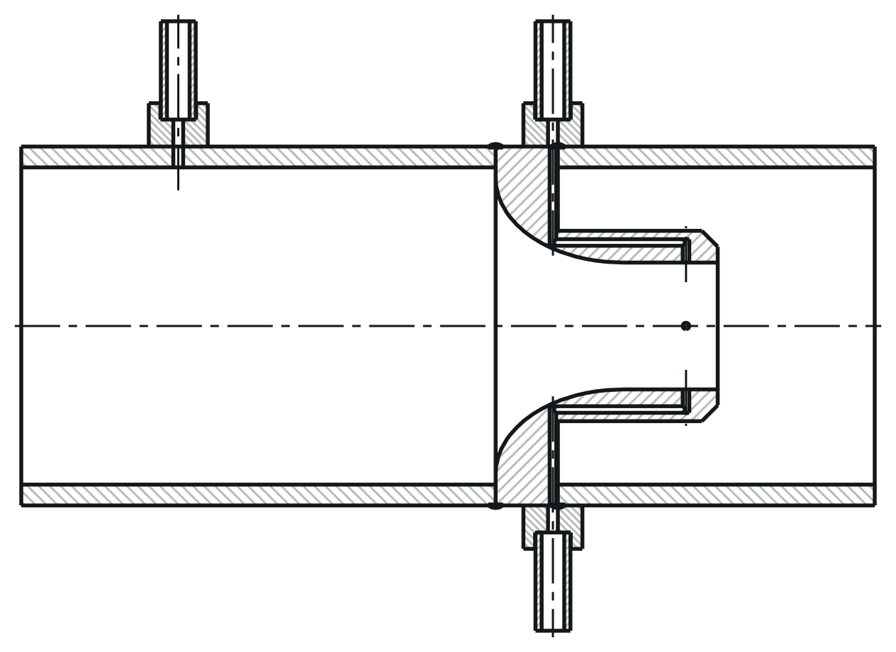
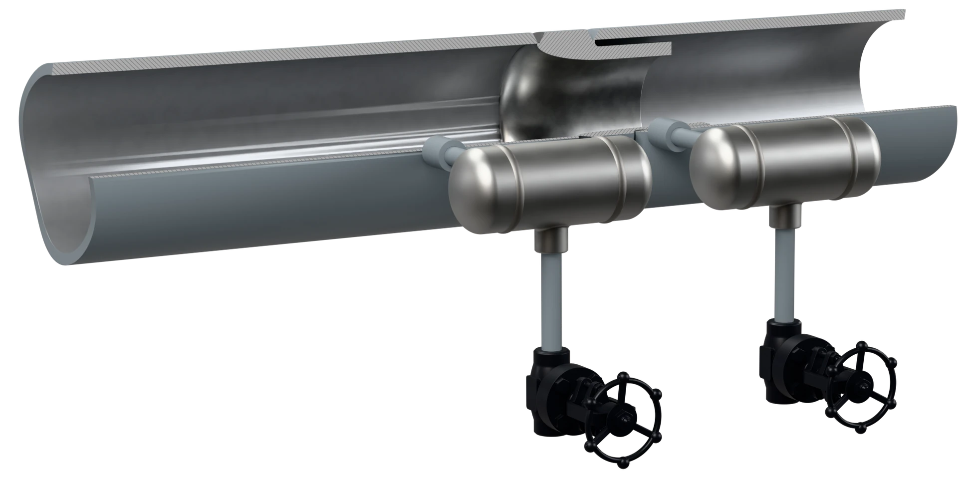
Throat Tap Nozzle
ISO 5167-3 · ASME PTC 6
Downstream tapping taken at the throat wall rather than the pipe. Built to ISO 5167-3, or as an ASME PTC 6 flow section for feedwater flow in turbine tests, calibrated with its pipe sections.
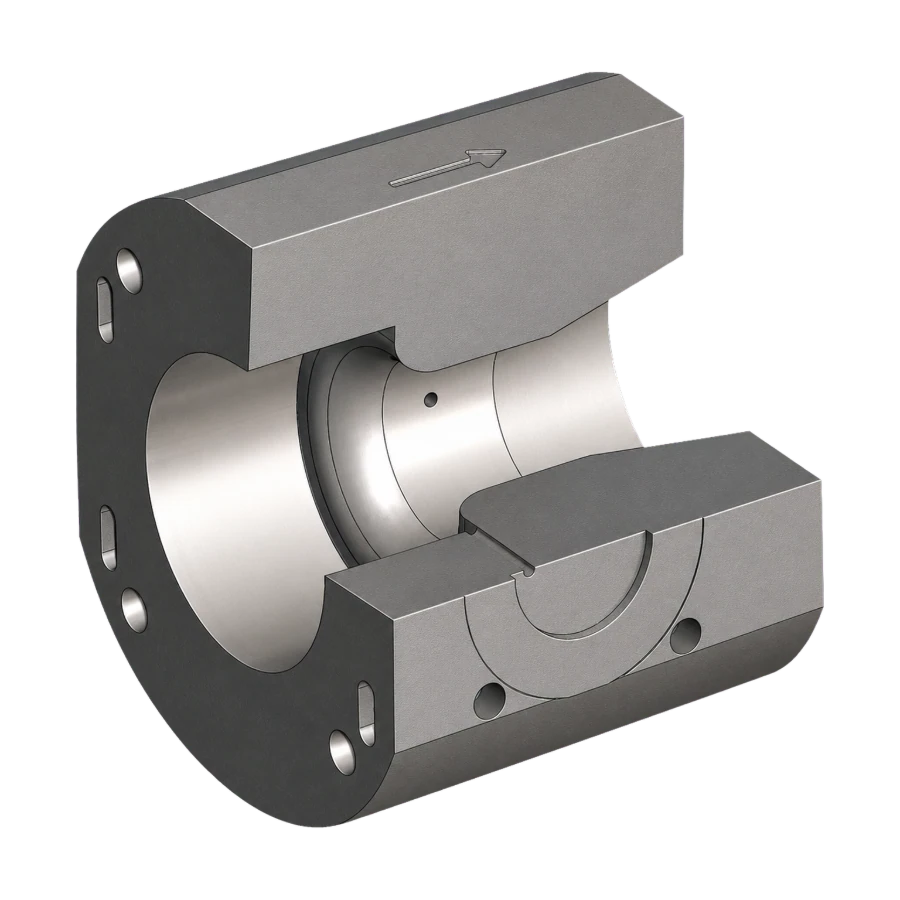
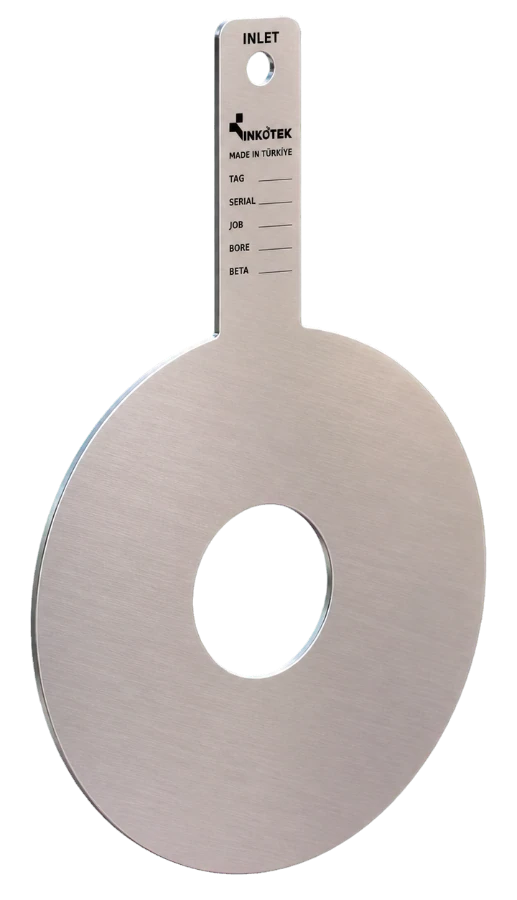
Wafer Nozzle Assembly
Held between line flanges
Nozzle carried in a wafer body clamped between the line flanges, with the tappings in the body: ISA-1932 or Venturi nozzle profile.
Technical data
| Size range | ISA-1932: DN 50 – DN 500 (2″ – 20″) · Long radius: DN 50 – DN 600 (2″ – 24″) · Throat tap: DN 100 – DN 600 (4″ – 24″) |
| Pressure class | ASME Class 150 – 2500 / EN 1092-1 PN 6 – PN 400; other flange standards to the project |
| Standards | ISO 5167-3, ASME MFC-3M; ASME PTC 6 for a calibrated throat tap flow section |
| Profiles | ISA-1932, long radius high and low ratio, throat tap |
| Beta ratio | 0.20 – 0.80 depending on profile |
| Construction | Welded into spool, flanged, or wafer between line flanges (wafer: ISA-1932 or Venturi nozzle) |
| Tappings | Corner, throat wall, or pipe wall as the profile requires |
| Measuring uncertainty | Stated on the calculation sheet for the duty; discharge coefficient uncertainty to ISO 5167-3 (ISA-1932 0.8 – 1.2 %, long radius 2.0 %) |
| Pressure loss | About 84 % of the differential at β 0.30, 61 % at 0.50, 25 % at 0.80 (ISO 5167-3, ISA-1932); long radius 92 % at β 0.20, 22 % at 0.80 |
| Installation thickness | Set per design and given on the drawing: ISA-1932 with its tapping holes or annular chamber, H ≤ 0.1D; long radius 3 mm ≤ H ≤ 0.15D (ISO 5167-3) |
| Marking | Tag number, pressure rating, size, throat diameter, material and flow direction; marking method to the project |
| Quality control | ISO 9001 system; PED where it applies; profile and throat measured and recorded; EN 10204 3.1 certificates, 3.2 on request |
| Documentation | Sizing calculation, profile inspection report, material certificate (EN 10204 3.1) |
Material selection
Two rules set the specification. The nozzle is chosen for wear and corrosion resistance; the spool is matched to the line pipe so the weld and the thermal expansion behave as one.
Where it runs
Sectors this family is specified into most often.
What to send for sizing
There is no dimension table for the family. Each nozzle is drawn for its line: the ISA-1932 installation thickness includes the tapping holes or the annular chamber, and the long radius thickness is set within the ISO 5167-3 limits. An installation drawing is issued as part of the project scope.
The throat diameter d is calculated from the process data you send. The calculation is part of the scope of supply.
Sizing enquiry sheet →| Process data | What it decides |
|---|---|
| Nozzle profile required | ISA-1932, long radius, throat tap or wafer construction |
| Line size and schedule | Sets the body and the throat diameter d |
| Flange standard, rating and facing | EN 1092-1 form or ASME B16.5 surface — or another standard you specify |
| Medium, phase and density | Steam, gas and liquid are sized differently |
| Flow range — min, normal, max | Sets β and the differential at each point |
| Pressure and temperature | Operating and design, both |
| Tapping interface required | Plain, butt weld, threaded, flanged, compact per IEC 61518 or compression fitting |
Documents
- Primary element: [ISA-1932 / long radius / throat tap] flow nozzle, line size [DN …], rating [Class … / PN …], β to suit the duty.
- Design: ISO 5167-3 / ASME MFC-3M; ASME PTC 6 for a calibrated throat tap flow section.
- Construction: [welded into a spool / flanged / wafer between line flanges]; installation thickness within ISO 5167-3 and given on the drawing.
- Tappings: [corner / throat wall / pipe wall], as the profile requires.
- Materials: [ … ], to suit the process and the line piping class.
- Marking: tag number, size, rating, throat diameter, material and flow direction.
- Inspection and documents: profile and throat measured and recorded; sizing calculation, profile inspection report, material certificate EN 10204 3.1 (3.2 where stated).
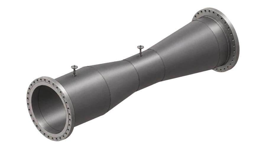
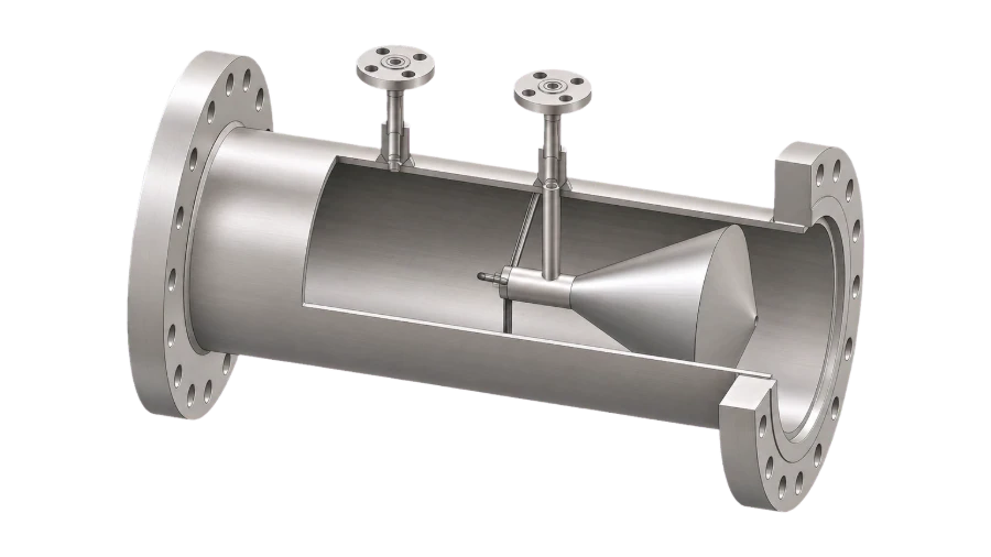
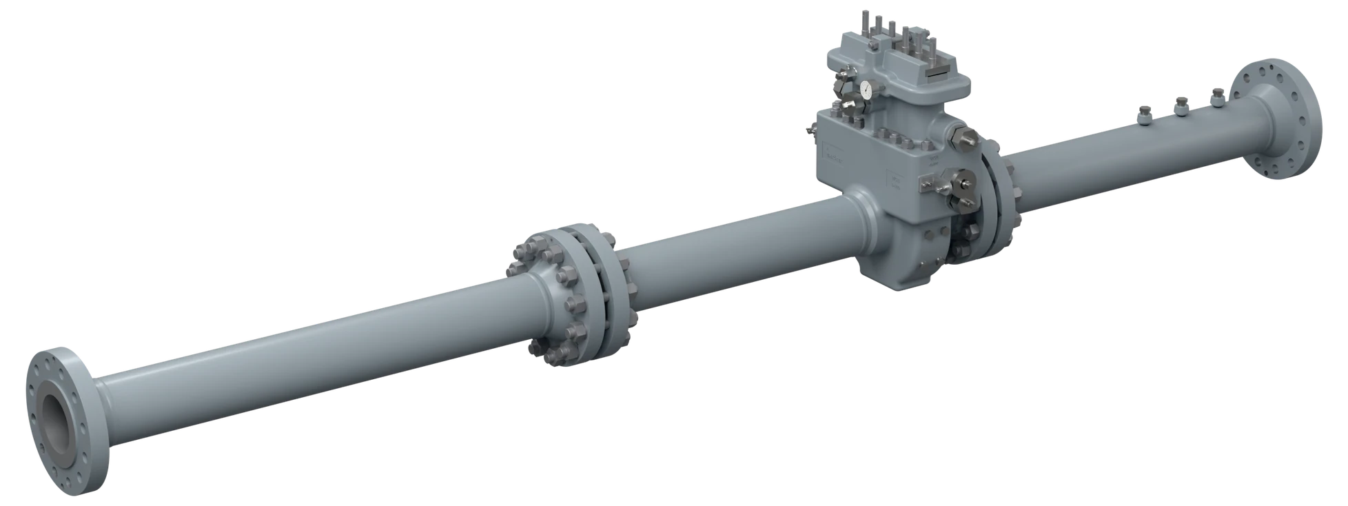
Flow Nozzles
Send the profile your specification calls for, the line size and the process data. If the specification is open, we will tell you which profile the duty actually wants.