
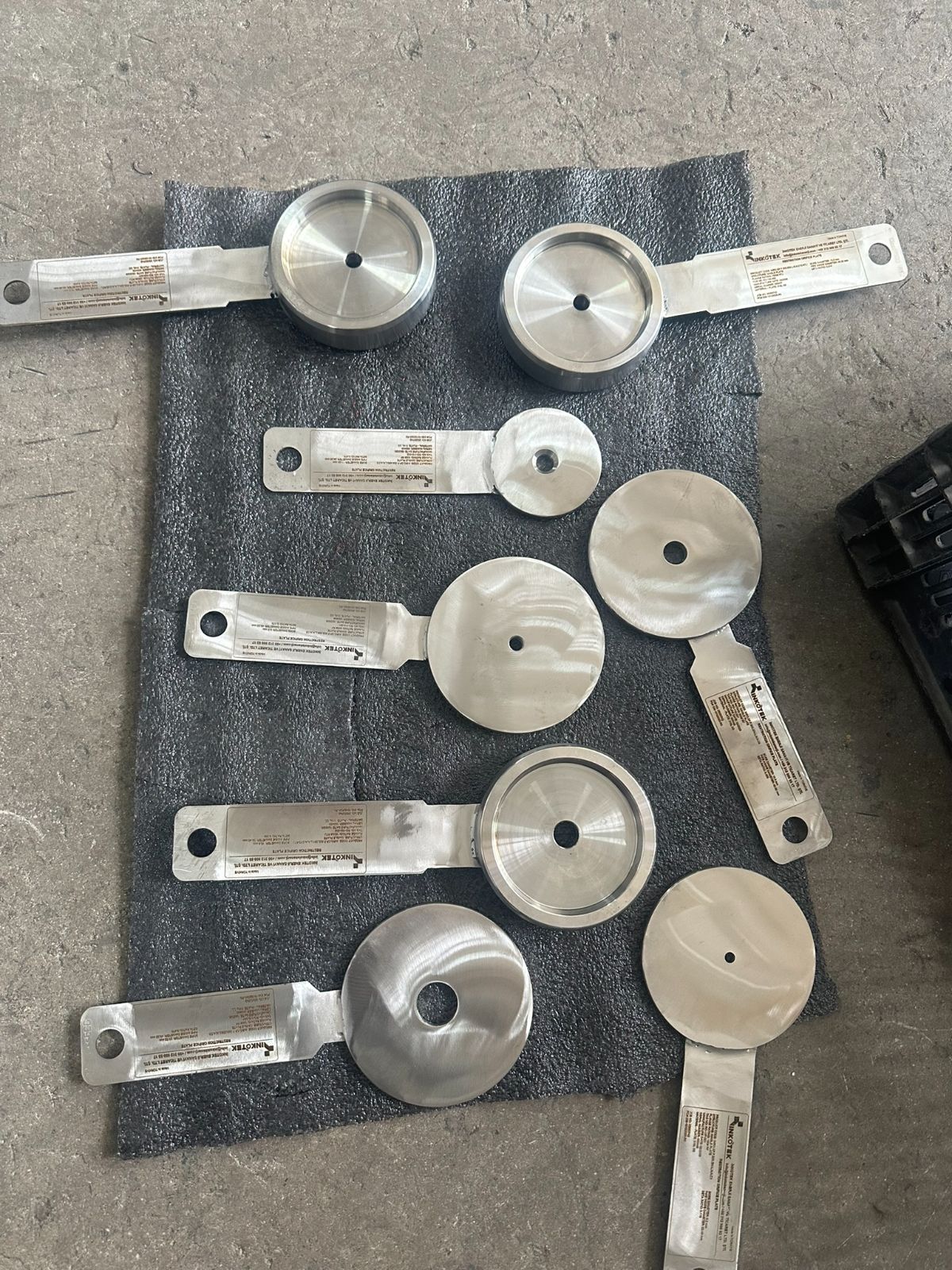
Restriction Orifices
A fixed restriction sized to take a known pressure drop out of the line and hold it there. No moving parts and no actuator; the plate is inspected whenever the line is opened. Where the required drop is large enough to cavitate, choke or generate noise, the drop is split across stages rather than taken in one plate. Where a single-stage choked flow restriction is preferred, it can be supplied to your specification.
One plate, or the drop split across several
The number of stages is not a preference, it is an outcome of the sizing. Once the downstream pressure approaches the vapour pressure of the liquid, or the gas velocity approaches sonic at the bore, a single plate stops being an option, unless the project accepts choked flow at the plate.
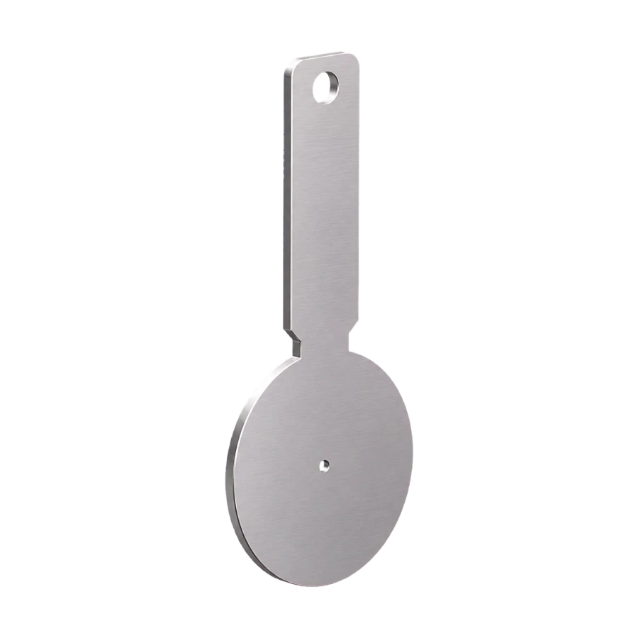
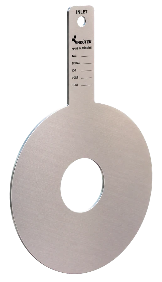
Single Stage Plate
One plate · fixed drop
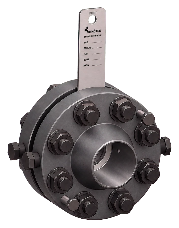
A single plate sized for the required drop. Used where one plate passes the cavitation, choking and noise checks, or, in gas service, as a choked flow-limiting plate where the project accepts it.
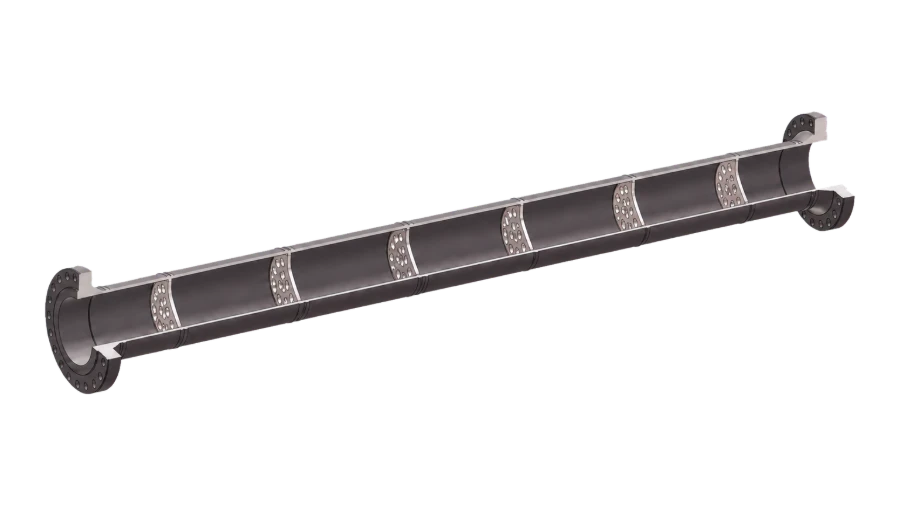
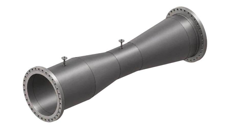
Multi-Stage Device
Staged drop
Several restrictions in series inside one body, each taking part of the drop so that no stage passes the cavitation limit or reaches critical flow. The stage plates are bolted in and removable.
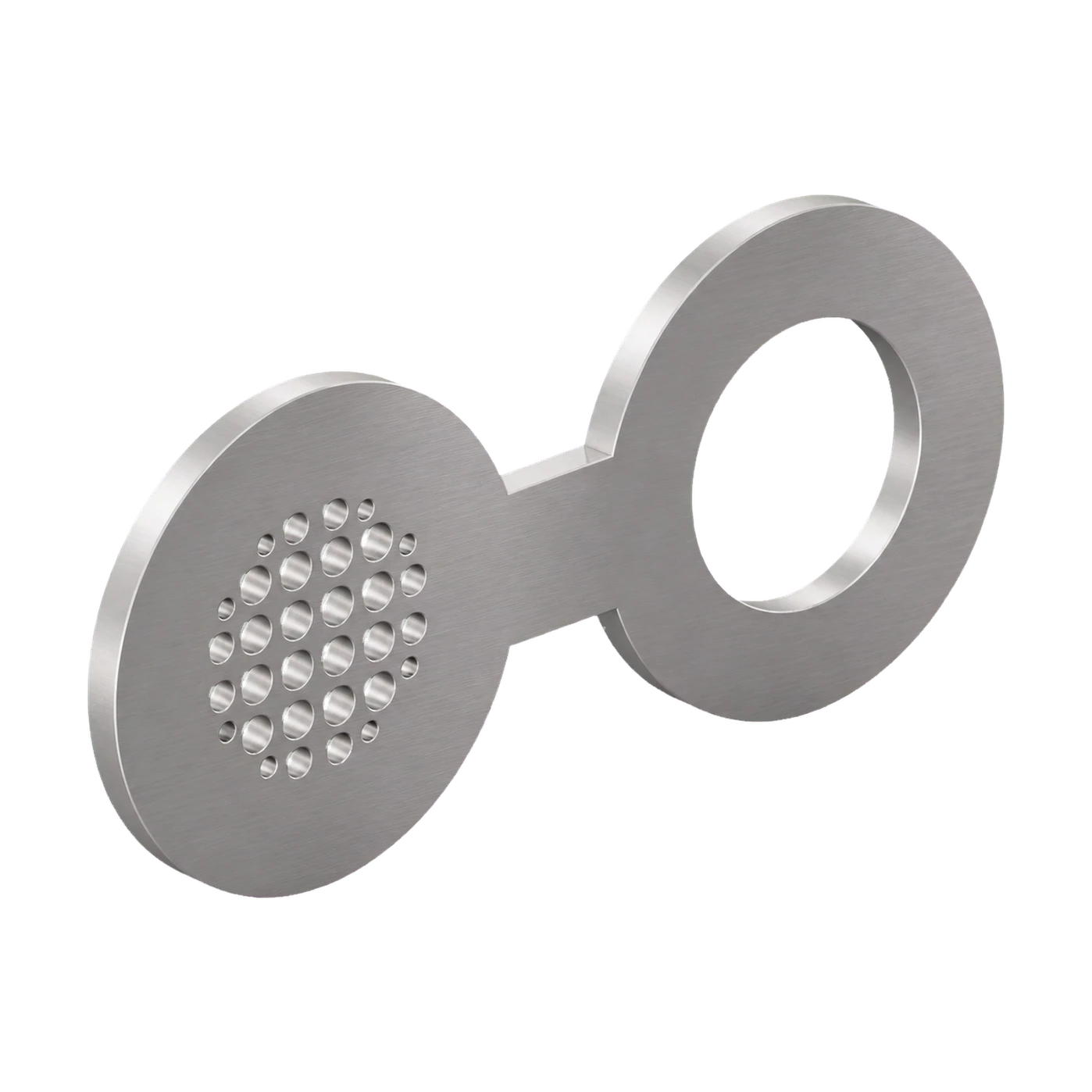
Spectacle Restriction Orifice
One piece · multi-hole plate and ring
One piece with a multi-hole restriction plate on one disc and a ring bored to the pipe on the other, joined across a short web. The hole pattern takes the drop while breaking the jet into many small streams, and the ring side keeps the flange gap when the restriction is not in the line. Outline to ASME B16.48.
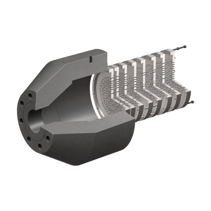
Attenuation Plate Set
Multi-hole · noise control
A multi-hole plate set installed downstream of a control valve, breaking the jet into many small streams and taking part of the drop.
The restriction orifice in 30 seconds
The single-stage plate and its fixed drop, single or multi-hole bores, the plate between flanges, and the multi-stage device that splits the drop — with the cavitation, choking and noise checks made for every stage.
30 s · no sound
Technical data
| Size range | NPS ½″ – 40″ (DN 15 – DN 1000), higher on request |
| Pressure class | ASME Class 150 – 2500 · EN 1092-1 PN 6 – PN 400 · other flange standards and special classes on request |
| Construction | Paddle or wafer plate, or spectacle plate, between the line flanges; plate supplied between its own flanges; wafer body; spool with bolted, removable stage plates |
| Stages | Set by the sizing calculation — single or multi-stage, by the cavitation and choking checks; noise checked against the limit |
| Stage spacing | At least 1D between stages in a multi-stage device |
| Bore pattern | Single bore or multi-hole |
| Liquid check | Cavitation index σ ≥ 2.0 unless the project sets another limit; choking to IEC 60534-2-1 |
| Gas check | Critical pressure ratio to IEC 60534-8-3 (5.1); a choked stage is sized on critical flow |
| Noise check | A-weighted sound pressure level 1 m from the downstream pipe wall, IEC 60534-8-3 method per stage, levels summed; 85 dB(A) unless the project sets another limit |
| Calculation output | Number of stages; bore, pressure drop and recovered pressure of each stage; cavitation index or critical pressure check per stage; sound pressure level at 1 m for gas and steam; plate thickness |
| Pressure loss | The design target rather than a by-product: the drop is set by the calculation, split across stages where a single plate would cavitate or choke |
| Marking | Tag and job number, bore or number of holes, material and flow direction; marking method to the project |
| Quality control | ISO 9001 system; PED where it applies; bore and hole pattern measured and recorded; positive material identification and penetrant testing where the project specifies; EN 10204 3.1 certificates, 3.2 on request |
| Sour service | Where sour service is specified: materials and hardness to NACE MR0175 / ISO 15156, hardness testing and positive material identification, and the documentation prepared to it |
| Documentation | Sizing calculation with the cavitation, choking and noise check, material certificate (EN 10204 3.1) |
Material selection
The plate takes the pressure drop and the cavitation; the carrier and flanges follow the line pipe.
Where it runs
Sectors this family is specified into most often.
What to send for sizing
The bore, the stage spacing and the number of stages come out of the sizing calculation, not from a catalogue table. Dimensions are issued on the approval drawing once the calculation is agreed.
Every type needs line size and schedule, flange standard and rating, medium, flow rate, upstream pressure and temperature, and the required downstream pressure. What each type needs beyond that is listed opposite.
Sizing enquiry sheet →| Type | Additional process data |
|---|---|
| Single Stage Restriction Orifice Plate | Allowable noise limit at the plate. State if a choked flow condition is acceptable or must be avoided. |
| Multi-Stage Restriction Device | Vapour pressure and specific heat ratio, allowable noise and cavitation limits, and the face-to-face length available in the line. |
| Spectacle Restriction Orifice | Flange standard, rating and facing, allowable noise limit, and whether the ring side is bored to the pipe ID. |
| Attenuation Plate Set | Valve type and Cv, distance from the valve outlet, and the allowable sound pressure level at the measuring point. |
Documents
- Restriction orifice: [single / multi]-stage, [single bore / multi-hole], [paddle / wafer / spectacle plate between line flanges / plate between its own flanges / spool with bolted stage plates]; line size [NPS …], rating [Class … / PN …].
- Sizing: number of stages set by the calculation. Liquid: cavitation index σ ≥ [2.0] and choking to IEC 60534-2-1. Gas: critical pressure ratio to IEC 60534-8-3; a choked stage sized on critical flow.
- Noise: A-weighted sound pressure level 1 m from the downstream pipe wall, by IEC 60534-8-3, not above [85 dB(A)].
- Stage spacing: at least 1D between stages in a multi-stage device.
- Materials: [ … ]; where sour service is stated, materials and hardness to NACE MR0175 / ISO 15156 with hardness testing and positive material identification.
- Marking: tag number, bore or number of holes, material and flow direction.
- Inspection and documents: bore and hole pattern measured and recorded; sizing calculation with the cavitation, choking and noise check; material certificate EN 10204 3.1 (3.2 where stated).
Restriction Orifices
Send the upstream and downstream pressure, the flow and the medium. We come back with the number of stages the duty needs, the bore for each and the noise check.